Robot grabbing mechanism

A grasping mechanism and robot technology, applied in the field of robots, can solve the problems of inconvenient packing operation, alignment and stacking of different objects, and achieve the effect of increasing distance, stable clamping process and increasing field of view

Inactive Publication Date: 2020-05-22
HARBIN UNIV OF COMMERCE
View PDF6 Cites 1 Cited by
  • Summary
  • Abstract
  • Description
  • Claims
  • Application Information

AI Technical Summary

Problems solved by technology

The utility model allows the positioning of the guide rail bar to have a position deviation before grabbing, and the grabbing part and the positioning part jointly adjust the guide rail bar when grabbing the guide rail bar, and the guide rail bar can be adjusted back to the preset installation posture to achieve precise installation , to ensure the installation quality of the electric control box; but this utility model is not convenient for packing different objects or performing alignment and stacking operations

Method used


Image

  • Robot grabbing mechanism
  • Robot grabbing mechanism
  • Robot grabbing mechanism

Examples


specific Embodiment approach 1

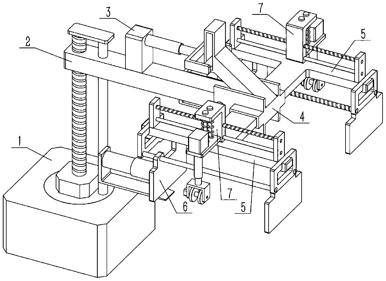
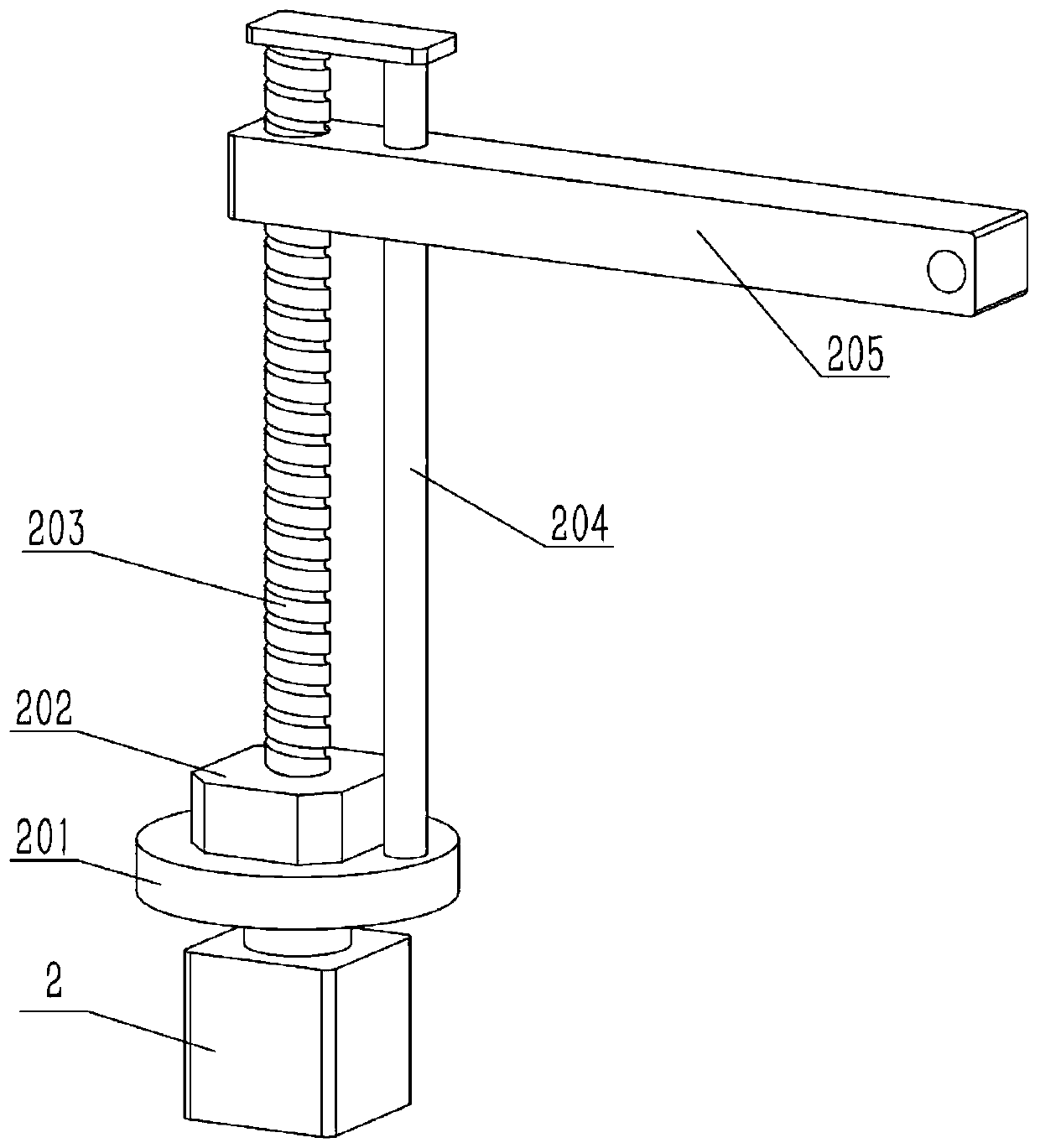
[0031] Such as Figure 1-10 As shown, a robot grabbing mechanism includes main arm 205, multi-joint frame 4, shaft II 401, inclined frame with groove 402, opening 403, T-beam 5, side safety frame 501, clamping part 502 and hand mechanism, the shaft II 401 is fixed on the left side of the multi-joint frame 4, the right side of the main arm 205 is rotationally connected with the shaft II 401, the upper end of the multi-joint frame 4 is fixedly connected with the inclined frame 402 with grooves, and the right side of the multi-joint frame 4 There is an opening 403, the one-way end of the T-beam 5 is located in the opening 403 and is fixedly connected with the multi-joint frame 4, the right end of the T-beam 5 is fixedly connected with a side frame 501, and the lower end of the side frame 501 is fixedly connected A clamping part 502, the distance between the hand mechanism and the clamping part 502 is adjustable, the hand mechanism can move with the movement of the T-beam 5, and t...

specific Embodiment approach 2

[0033] Such as Figure 1-10 As shown, the robot grabbing mechanism also includes a lead screw II 504, a round steel II 505 and an active part 6. The left end of the multi-joint frame 4 is fixed to a side frame 501, and the motor III 503 is fixed to the side frame 501 at the left end. Above, the output shaft of the motor III 503 is fixedly connected to the lead screw II 504, the two ends of the lead screw II 504 are respectively connected to the two side mounting frames 501 in rotation, and the two ends of the round steel II 505 are respectively fixed to the two side mounting frames 501, The hand mechanism includes an active part 6 , the upper side of the active part 6 is threadedly connected with the screw II 504 , and the upper side of the active part 6 is slidably connected with the round steel II 505 . Start the motor III 503, the motor III 503 drives the lead screw II 504 to rotate, and the lead screw II 504 drives the active part 6 to move left and right, and then adjust ...

specific Embodiment approach 3

[0035] Such as Figure 1-10 As shown, the robot grabbing mechanism also includes an electric push rod II 601 and an entry bracket 602. The fixed end of the electric push rod II 601 is fixedly connected to the left end of the active part 6, and the movable end of the electric push rod II 601 is connected to the entry bracket 602. The left end of the bracket 602 is fixed, and the lower end structure of the bracket 602 is located below the moving part 6 . refer to Figure 10 , the dotted line part is the object in the cargo compartment, and the dotted line part between the active part 6 and the clamping part 502 is the clamped object. When the object enters obliquely, the center of gravity is shifted to the left due to the inclination, so as to avoid the clamping force If it is too large, the clamped item will be damaged, or to prevent the clamped item from falling off, use the bracket 602 that can move left and right to hold up the clamped item, start the electric push rod II 6...


PUM


Abstract

The invention relates to the field of robots, in particular to a robot grabbing mechanism. The robot grabbing mechanism comprises a main arm, a multi-joint frame, a shaft II, a groove-containing inclined frame, a through opening, a T-shaped beam, side mounting frames, a fixing and clamping portion and a hand mechanism, wherein parts above the fixing and clamping portion and on the left side of thefixing and clamping portion can be integrally lowered by anticlockwise inclining the fixing and clamping portion and a driving portion, the distance for an object to enter a cargo compartment can beincreased, the view field in the compartment is increased, and the clamped object can be conveniently stacked in the cargo compartment; by means of the identification and object abutting of the fixingand clamping portion, the object cannot move in the object clamping process in combination with the independently-moving driving portion, the clamping process is stabler, and the object can be placedand aligned by means of the independently-moving driving portion; and guide wheels are used for being in contact with a circular-tube-shaped object and rotates to drive the circular-tube-shaped object to move front and back, and loading and unloading operation of the circular-tube-shaped object is assisted.

Description

technical field [0001] The invention relates to the field of robots, in particular to a robot grabbing mechanism. Background technique [0002] For example, the publication number is CN209125855U, a robot grabbing device and a robot with the robot grabbing device. The robot grabbing device is connected to the robot arm. The robot grabbing device includes: grabbing parts and a cylinder, and the cylinder has at least a movable Two fingers, the plunger movement of the cylinder drives the fingers to change the distance, the grasping parts include claws, the claws are fixedly connected to the fingers, and the claws correspond to the fingers one by one, and the claws are driven by the fingers to adjust the distance; positioning The positioning piece is fixed on the cylinder, and the positioning piece is located between the claws. The side of the positioning piece opposite to the cylinder is provided with an adsorption device. The adsorption device is embedded in the positioning pi...

Claims


Application Information

Patent Timeline
Patent Type & Authority Applications(China)
IPC IPC(8): B25J15/00B25J15/08
CPCB25J15/00B25J15/08
Inventor 李晖
Owner HARBIN UNIV OF COMMERCE
Why Eureka
Try Eureka