A robot grabbing mechanism
A grasping mechanism and robot technology, applied in the field of robots, can solve the problems of inconvenient packing operation, alignment and stacking of different objects, and achieve the effect of increasing the distance, increasing the field of view, and stabilizing the clamping process
- Summary
- Abstract
- Description
- Claims
- Application Information
AI Technical Summary
Problems solved by technology
Method used
Image
Examples
specific Embodiment approach 1
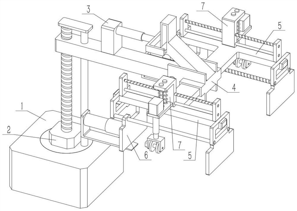
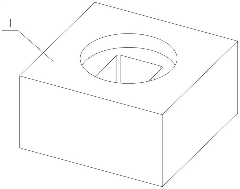
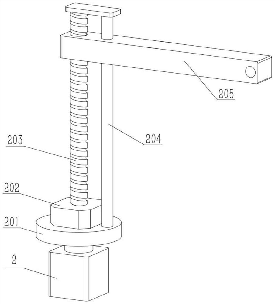
[0031] Such as Figure 1-10 As shown, a robot grabbing mechanism includes main arm 205, multi-joint frame 4, shaft II 401, inclined frame with groove 402, opening 403, T-beam 5, side safety frame 501, clamping part 502 and hand mechanism, the shaft II 401 is fixed on the left side of the multi-joint frame 4, the right side of the main arm 205 is rotationally connected with the shaft II 401, the upper end of the multi-joint frame 4 is fixedly connected with the inclined frame 402 with grooves, and the right side of the multi-joint frame 4 There is an opening 403, the one-way end of the T-beam 5 is located in the opening 403 and is fixedly connected with the multi-joint frame 4, the right end of the T-beam 5 is fixedly connected with a side frame 501, and the lower end of the side frame 501 is fixedly connected A clamping part 502, the distance between the hand mechanism and the clamping part 502 is adjustable, the hand mechanism can move with the movement of the T-beam 5, and t...
specific Embodiment approach 2
[0033] Such as Figure 1-10 As shown, the robot grabbing mechanism also includes a lead screw II 504, a round steel II 505 and an active part 6. The left end of the multi-joint frame 4 is fixed to a side frame 501, and the motor III 503 is fixed to the side frame 501 at the left end. Above, the output shaft of the motor III 503 is fixedly connected to the lead screw II 504, the two ends of the lead screw II 504 are respectively connected to the two side mounting frames 501 in rotation, and the two ends of the round steel II 505 are respectively fixed to the two side mounting frames 501, The hand mechanism includes an active part 6 , the upper side of the active part 6 is threadedly connected with the screw II 504 , and the upper side of the active part 6 is slidably connected with the round steel II 505 . Start the motor III 503, the motor III 503 drives the lead screw II 504 to rotate, and the lead screw II 504 drives the active part 6 to move left and right, and then adjust ...
specific Embodiment approach 3
[0035] Such as Figure 1-10 As shown, the robot grabbing mechanism also includes an electric push rod II 601 and an entry bracket 602. The fixed end of the electric push rod II 601 is fixedly connected to the left end of the active part 6, and the movable end of the electric push rod II 601 is connected to the entry bracket 602. The left end of the bracket 602 is fixed, and the lower end structure of the bracket 602 is located below the moving part 6 . refer to Figure 10 , the dotted line part is the object in the cargo compartment, and the dotted line part between the active part 6 and the clamping part 502 is the clamped object. When the object enters obliquely, the center of gravity is shifted to the left due to the inclination, so as to avoid the clamping force If it is too large, the clamped item will be damaged, or to prevent the clamped item from falling off, use the bracket 602 that can move left and right to hold up the clamped item, start the electric push rod II 6...
PUM
 Abstract
Description
Claims
Application Information
 - R&D
- Intellectual Property
- Life Sciences
- Materials
- Tech Scout
- Unparalleled Data Quality
- Higher Quality Content
- 60% Fewer Hallucinations
Browse by: Latest US Patents, China's latest patents, Technical Efficacy Thesaurus, Application Domain, Technology Topic, Popular Technical Reports.
© 2025 PatSnap. All rights reserved.Legal|Privacy policy|Modern Slavery Act Transparency Statement|Sitemap|About US| Contact US: help@patsnap.com


