A household formaldehyde remover

A cleaner and formaldehyde technology, applied in the direction of gas treatment, chemical instruments and methods, separation methods, etc., can solve the problems of dust adhesion and difficult cleaning of ventilation pipes, etc.

Active Publication Date: 2021-12-14
福建泉州台商投资区莉沓科技有限公司
View PDF18 Cites 0 Cited by
  • Summary
  • Abstract
  • Description
  • Claims
  • Application Information

AI Technical Summary

Problems solved by technology

[0003] Based on the discovery of the above-mentioned inventors, the existing household formaldehyde cleaner mainly has the following shortcomings, such as: when the equipment absorbs formaldehyde in the air, the dust in the air will also follow into the equipment, when the dust passes through The vent pipe is in contact with the oxidant evaporated by heat, which will cause the dust to adhere to the vent pipe, making it difficult to clean the vent pipe

Method used


Image

  • A household formaldehyde remover
  • A household formaldehyde remover
  • A household formaldehyde remover

Examples


Embodiment 1

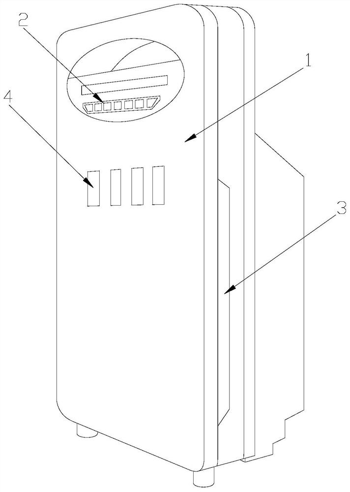
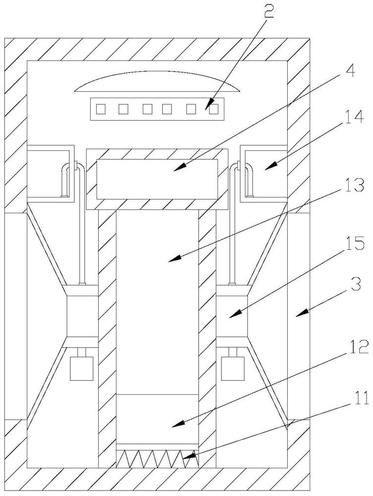
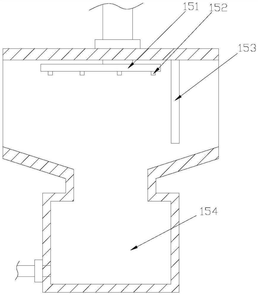
[0024] Example 1: Please refer to Figure 1-Figure 4 The specific embodiment of the present invention is as follows: its structure includes a main body 1, a control panel 2, an air inlet 3, and an air outlet 4, the upper front end of the main body 1 is provided with a control panel 2, and the air inlet 3 is arranged on the side The air outlet 4 is located directly below the control panel 2. The main body 1 includes a heating wire 11, an oxidant storage tank 12, a ventilation pipe 13, a water tank 14, and a vent 15. The heating wire 11 is installed on the main body 1. In the middle of the bottom, the oxidant storage tank 12 is arranged on the top of the heating wire 11, the ventilation pipe 13 is nested on the upper end of the oxidant storage tank 12, and two water tanks 14 are provided, and the water tanks 14 are respectively arranged on the main body 1, the vent 15 is located at the side end of the vent pipe 13, the vent 15 is provided with two, and the vent 15 is respectivel...

Embodiment 2

[0028] Example 2: Please refer to Figure 5-Figure 7 The specific embodiment of the present invention is as follows: the baffle a3 includes a support block a31, a dust shield a32, and a first spring a33, the inner side of the support block a31 is engaged with a dust shield a32, and the first spring a33 is installed In the support block a31, the first spring a33 is movably matched with the dust shield a32, which is beneficial for the first spring a33 to support the dust shield a32 to shield the through hole a2 from dust.

[0029] The dust shield a32 is composed of a first plate body b1, a sliding groove b2, a second spring b3, a second plate body b4, a third spring b5, and a clamping rod b6, and a sliding groove is provided on the inside of the first plate body b1 b2, the second spring b3 is installed inside the sliding groove b2, the second plate b4 is arranged at the side end of the first plate b1, and the bottom of the side end of the second plate b4 is connected with the th...


PUM


Abstract

The invention discloses a household formaldehyde remover, the structure of which includes a main body, a control panel, an air inlet, and an air outlet. The main body includes a heating wire, an oxidant storage tank, a ventilation pipe, a water tank, and an air vent. In the middle, the oxidant storage tank is set on the top of the heating wire; the vent includes a spray pipe, an atomizing nozzle, a filter plate, and a water storage tank; the filter plate includes a water tank and a through hole; the through hole includes a support block, a dust shield, and a support block It is arranged at the side end of the through hole, the dust shield is installed in the support block, and the dust shield is movably engaged with the support block; the present invention degrades the dust in the air by spraying water from the atomizing nozzle, and The filter plate at the end of the tuyere is set in a through hole inclined at 30 degrees from the horizontal plane, so that the gaseous formaldehyde can pass through the solid dust that has not been degraded, and avoid the situation where the dust is attached to the ventilation pipe through the through hole, which makes it difficult to clean the dust Case.

Description

technical field [0001] The invention relates to the field of formaldehyde treatment, in particular to a household formaldehyde cleaner. Background technique [0002] In a house that has just been painted, the content of formaldehyde is often relatively high. It is necessary to install a formaldehyde cleaner in the house in advance to clean up the formaldehyde, so as to prevent people from inhaling formaldehyde and affecting their health; Inhaled into the equipment together with formaldehyde, the oxidant is heated through the heating wire, and the oxidant evaporates and contacts with formaldehyde, which can achieve the effect of decomposing formaldehyde, thereby reducing the concentration of formaldehyde in the air. [0003] Based on the discovery of the above-mentioned inventors, the existing household formaldehyde cleaner mainly has the following shortcomings, such as: when the equipment absorbs formaldehyde in the air, the dust in the air will also follow into the equipmen...

Claims


Application Information

Patent Timeline
Patent Type & Authority Patents(China)
IPC IPC(8): B01D50/00B01D53/72B01D53/76
CPCB01D53/72B01D53/76B01D2257/704B01D2259/4508B01D50/10
Inventor 瞿鹏业
Owner 福建泉州台商投资区莉沓科技有限公司
Why Eureka
Try Eureka