Display panel and display device

A display panel and display area technology, applied in the direction of identification devices, instruments, etc., can solve the problems of inconspicuous improvement, achieve the effect of improving display performance and weakening the jagged phenomenon

Active Publication Date: 2022-02-25
WUHAN TIANMA MICRO ELECTRONICS CO LTD
View PDF0 Cites 0 Cited by
  • Summary
  • Abstract
  • Description
  • Claims
  • Application Information

AI Technical Summary

Problems solved by technology

[0003] However, after digging out some pixels in the optical component setting area, there will be a more obvious jagged feeling at the junction of the optical component setting area and the conventional display area. Therefore, in the prior art, usually by changing the shape of the sub-pixel, For example, setting the sub-pixels as circles or squares, or changing the arrangement of sub-pixels to reduce the jaggedness, but the improvement effect is not obvious

Method used


Image

  • Display panel and display device
  • Display panel and display device
  • Display panel and display device

Examples


Embodiment Construction

[0028] In order to better understand the technical solutions of the present invention, the embodiments of the present invention will be described in detail below in conjunction with the accompanying drawings.

[0029] It should be clear that the described embodiments are only some of the embodiments of the present invention, not all of them. Based on the embodiments of the present invention, all other embodiments obtained by persons of ordinary skill in the art without creative efforts fall within the protection scope of the present invention.

[0030] Terms used in the embodiments of the present invention are only for the purpose of describing specific embodiments, and are not intended to limit the present invention. As used in the embodiments of the present invention and the appended claims, the singular forms "a", "said" and "the" are also intended to include the plural forms unless the context clearly indicates otherwise.

[0031] It should be understood that the term "an...


PUM


Abstract

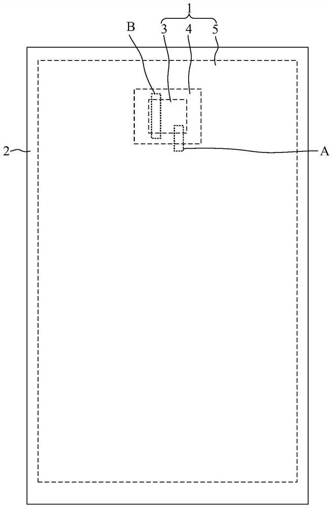
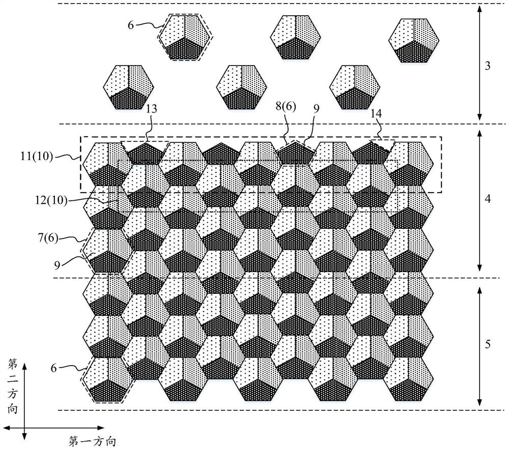
Embodiments of the present invention provide a display panel and a display device, which relate to the field of display technology and reduce the jagged phenomenon. The display panel includes: a display area, including an optical component setting area, a transition area, and a main display area; display pixels, including a first pixel composed of n sub-pixels and a second pixel composed of m sub-pixels, n>m≥1; The first pixel constitutes a pixel group, and the first pixels in adjacent pixel groups are dislocated and meshed; the pixel group closest to the optical component setting area in the transition area is the first pixel group, and the pixel group adjacent to the first pixel group is the second pixel group. The pixel group, the first pixel of the first pixel group and the second pixel group form the first sawtooth part; the second pixel is located in the first sawtooth part, and the second pixel and the first pixel form the second sawtooth part; the maximum width of the second sawtooth part less than the maximum width of the first serration, and / or, the maximum depth of the second serration is smaller than the maximum depth of the first serration.

Description

【Technical field】 [0001] The present invention relates to the field of display technology, in particular to a display panel and a display device. 【Background technique】 [0002] In order to realize the camera function of the display panel, the display area of ​​the display panel is provided with an optical component setting area for placing the camera assembly. At present, in order to improve the light transmittance of the optical component setting area and optimize the imaging quality, usually in the optical component setting area Part of the pixels are dug out to reduce the pixel density in the optical component setting area. [0003] However, after digging out some pixels in the optical component setting area, there will be a more obvious jagged feeling at the junction of the optical component setting area and the conventional display area. Therefore, in the prior art, usually by changing the shape of the sub-pixel, For example, setting the sub-pixels to be circular or s...

Claims


Application Information

Patent Timeline
Patent Type & Authority Patents(China)
IPC IPC(8): G09F9/30
CPCG09F9/30
Inventor 张建业
Owner WUHAN TIANMA MICRO ELECTRONICS CO LTD
Why Eureka
Try Eureka