
Threshing roller having adjustable diameter

A threshing drum and adjustable technology, applied in the field of agricultural machinery, can solve the problems of fixed drum diameter, affecting threshing quality, and grain loss, etc., to achieve the effects of simple and convenient adjustment operation, good threshing quality and strong adaptability

Pending Publication Date: 2020-09-01
NORTHEAST AGRICULTURAL UNIVERSITY
View PDF0 Cites 0 Cited by
  • Summary
  • Abstract
  • Description
  • Claims
  • Application Information

AI Technical Summary

Problems solved by technology

[0002] Traditional threshing cylinders, including the bar-shaped threshing cylinder, the spike-toothed threshing cylinder, and the bow-toothed threshing cylinder, cannot realize the adjustment and change of the diameter of the cylinder, that is, the diameter of the cylinder is fixed.
In the actual threshing operation, since the diameter of the drum cannot be changed, the threshing distance between the drum and the threshing concave plate is fixed. When the output of the threshed grain is different or the feeding amount is different, it will affect the threshing quality, including the cleaning rate. and grain breakage rate and other operating indicators
When the crop yield is low or the amount of feed is low, the operating efficiency of the machine tool will decrease, and the cost of threshing operation will increase; when the crop yield is high or the amount of feed is large, the cleaning rate and grain recovery rate will decrease, and the grain breakage rate will increase, resulting in grain loss

Method used


Image

  • Threshing roller having adjustable diameter

Examples


Embodiment Construction

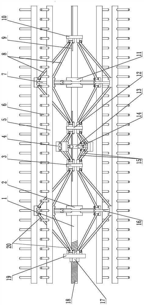
[0009] Embodiments of the present invention will be described in detail below in conjunction with the accompanying drawings. A diameter-adjustable threshing drum, including a tooth seat plate 5, on which a threshing nail tooth 6 is fixed, and a screw thread 18 and an axial slideway groove 9 are respectively arranged on the left end and the right end of the drum shaft 1, On the drum shaft 1, the adjusting nut 17, the adjusting drive plate 19, the left supporting seat 2, the left sliding seat 3, the transition connection supporting seat 13, the right sliding seat 12, the right supporting seat 11 and the To adjust the follower plate 10, the adjusting nut 17 is rotatably matched with the screw thread 18, the adjusting nut 17 is locked radially and axially with the adjusting driving plate 19, and is connected rotatably in the circumferential direction, the adjusting driving plate 19, the left sliding seat 3. The right sliding seat 12 and the adjusting follower plate 10 are locked r...


PUM


Abstract

The invention relates to a threshing roller having adjustable diameter, and belongs to agricultural machinery. A thread and an axial chute groove are respectively formed in the left end and the rightend of a roller shaft, an adjusting nut, an adjusting driving disc, a left supporting seat, a left sliding seat, a transitional connecting supporting seat, a right sliding seat, a right supporting seat and an adjusting follow-up disc are sequentially arranged on the roller shaft in a sleeving manner from left to right, a telescopic left supporting rod is fixedly mounted on the left supporting seat, a telescopic middle supporting rod is fixedly mounted on the transitional connecting supporting seat, and a telescopic right supporting rod is fixedly mounted on the right supporting seat; and connecting blocks are fixedly mounted at external ends of the telescopic middle supporting rod, tooth seat plates are hinged to the adjusting driving disc and the left sliding seat respectively through left connecting rods, and are hinged to the adjusting follow-up disc and the right sliding seat respectively through right connecting rods, and the connecting blocks are respectively hinged to the left sliding seat and the right sliding seat through central connecting rods. The diameter of the threshing roller can be adjusted according to needs of threshing tasks, and the threshing roller is novel, unique and reasonable in structure, simple and convenient in adjustment operations, high in adaptability, high in working performance and good in threshing quality.

Description

technical field [0001] The invention belongs to agricultural machinery, and mainly relates to a diameter-adjustable threshing drum. Background technique [0002] Traditional threshing cylinders, including the bar-shaped threshing cylinder, the spike-toothed threshing cylinder, and the bow-toothed threshing cylinder, cannot realize the adjustment and change of the cylinder diameter, that is, the diameter of the cylinder is fixed. In the actual threshing operation, since the diameter of the drum cannot be changed, the threshing distance between the drum and the threshing concave plate is fixed. When the output of the threshed grain is different or the feeding amount is different, the threshing quality is affected, including the cleaning rate. and grain breakage rate and other operating indicators. When the crop yield is low or the feeding amount is small, the operating efficiency of the machine tool decreases and the cost of threshing operation increases; when the crop yield ...

Claims


Application Information

Patent Timeline
Patent Type & Authority Applications(China)
IPC IPC(8): A01F12/22A01F12/18
CPCA01F12/181A01F12/22
Inventor 唐汉王金武徐常塑李革王丽娟孙小博姜岩
Owner NORTHEAST AGRICULTURAL UNIVERSITY
Learn More