Rigid-flexible coupling double-drive pneumatic gripper

A rigid-flexible coupling, pneumatic unit technology, used in manipulators, manufacturing tools, chucks, etc., can solve the problem that it is difficult to further increase the grasping upper limit of the soft gripper, the rigidity of the soft gripper is limited, and the position accuracy of the grasped object is high. problems, to achieve good grasping fit, wide grasping quality range, and good grasping fit

Active Publication Date: 2020-09-04
HUAZHONG UNIV OF SCI & TECH
View PDF9 Cites 2 Cited by
  • Summary
  • Abstract
  • Description
  • Claims
  • Application Information

AI Technical Summary

Problems solved by technology

[0003] Most of the existing grippers are based on fully rigid structures, which have defects such as high requirements for the position accuracy of the grasped objects, difficulty in grasping fragile objects, and poor interaction capabilities.
The emerging soft robot gripper benefits from the softness of soft materials, which has natural adaptability and interactive capabilities, and can complete tasks that are difficult for rigid grippers (such as grasping fragile objects such as cakes and jellies) through a relatively simple structure. But it also has the defect that the gripping force is too small
The existing main idea to solve this problem is to introduce variable stiffness mechanisms such as particle blockage and low-melting point alloys to change the stiffness of the soft gripper, but on the one hand, this will introduce unnecessary time-consuming stiffness changes, and on the other hand The improvement of the stiffness of the soft gripper is also relatively limited
[0004] In summary, there is still a lack of a soft gripper with a larger gripping range, and it is difficult to further increase the gripping limit of the soft gripper by using the existing variable stiffness mechanism and design concept

Method used


Image

  • Rigid-flexible coupling double-drive pneumatic gripper
  • Rigid-flexible coupling double-drive pneumatic gripper
  • Rigid-flexible coupling double-drive pneumatic gripper

Examples


Embodiment Construction

[0029] In order to make the object, technical solution and advantages of the present invention clearer, the present invention will be further described in detail below in conjunction with the accompanying drawings and embodiments. It should be understood that the specific embodiments described here are only used to explain the present invention, not to limit the present invention. In addition, the technical features involved in the various embodiments of the present invention described below can be combined with each other as long as they do not constitute a conflict with each other.

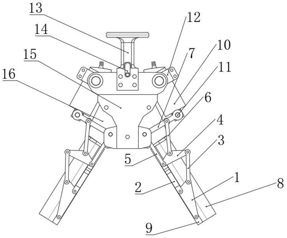
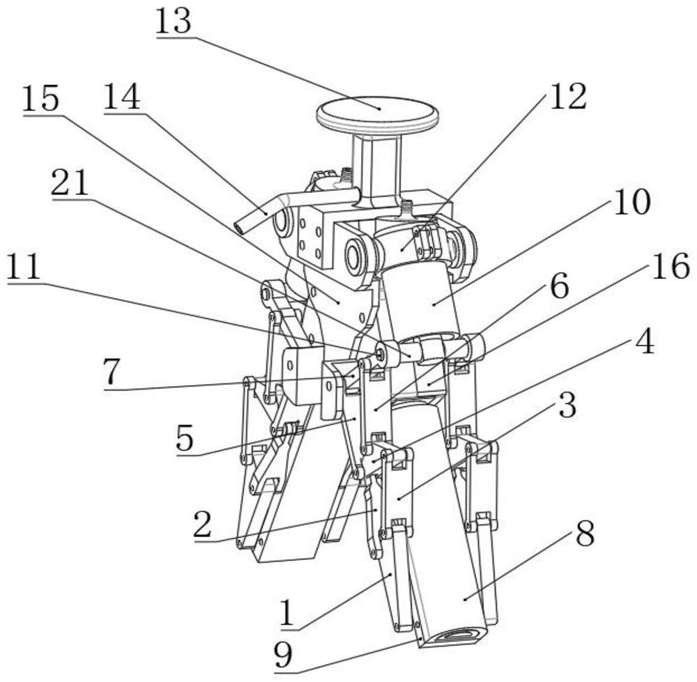
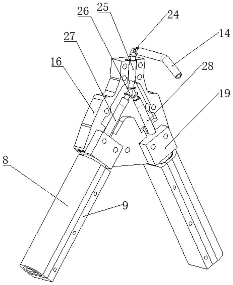
[0030] like Figure 1~3 As shown, the embodiment of the present invention provides a rigid-flexible dual-drive pneumatic gripper, which includes a support device, a gripper device and a drive device connected to the support device, wherein:

[0031]The gripper device includes a rigid gripper unit and a soft gripper unit. The rigid gripper unit and the soft gripper unit are connected in parallel...


PUM


Abstract

The invention belongs to the field of mechanical grippers, and particularly discloses a rigid-flexible coupling double-drive pneumatic gripper. The gripper comprises a supporting device, a gripper device and a driving device, wherein the gripper device and the driving device are connected with the supporting device; the gripper device comprises a rigid gripper unit and a soft gripper unit which are connected in parallel, when a fragile object is gripped, the soft gripper unit is active and the rigid gripper unit is passive, and when a heavy object is grabbed, the rigid gripper unit is active and the soft gripper unit is passive; and the driving device comprises a first pneumatic unit and a second pneumatic unit, the first pneumatic unit is used for driving the rigid gripper unit, and the second pneumatic unit is used for driving the soft gripper unit. The rigid-flexible coupling double-drive pneumatic gripper has the advantages of being large in grabbing mass range and good in grabbingattachment performance, and the grabbing mass and the grabbing attachment degree of the rigid-flexible coupling double-drive pneumatic gripper can be adjusted and controlled by adjusting the drivingproportion of the first pneumatic unit and the second pneumatic unit.

Description

technical field [0001] The invention belongs to the field of mechanical grippers, and more specifically relates to a rigid-flexible coupling dual-drive pneumatic gripper. Background technique [0002] With the innovation and development of technology, all kinds of mechanical grippers have been created and used to adapt to various working environments. Among them, the newly emerging software robot gripper has gradually entered people's field of vision due to its excellent environmental adaptability and interaction ability. [0003] Most of the existing grippers are based on fully rigid structures, which have defects such as high requirements for the position accuracy of the grasped objects, difficulty in grasping fragile objects, and poor interaction capabilities. The emerging soft robot gripper benefits from the softness of soft materials, which has natural adaptability and interactive capabilities, and can complete tasks that are difficult for rigid grippers (such as grasp...

Claims


Application Information

Patent Timeline
Patent Type & Authority Applications(China)
IPC IPC(8): B25J15/08B25J15/12
CPCB25J15/08B25J15/12
Inventor 吴志刚朱嘉淇祝子位
Owner HUAZHONG UNIV OF SCI & TECH
Why Eureka
Try Eureka