Brake pedal assembly and vehicle

A technology of brake pedals and components, which is applied to vehicle components, foot-operated starting devices, optical signals, etc., and can solve the problems that the brake light switch cannot be turned on and off normally.

Inactive Publication Date: 2020-09-04
GREAT WALL MOTOR CO LTD
View PDF4 Cites 0 Cited by
  • Summary
  • Abstract
  • Description
  • Claims
  • Application Information

AI Technical Summary

Problems solved by technology

[0004] In view of this, the present invention aims to propose a brake pedal assembly to solve the proble

Method used


Image

  • Brake pedal assembly and vehicle
  • Brake pedal assembly and vehicle
  • Brake pedal assembly and vehicle

Examples


Embodiment Construction

[0028] It should be noted that, in the case of no conflict, the embodiments and features in the embodiments of the present invention can be combined with each other.

[0029] The present invention will be described in detail below with reference to the drawings and in combination with embodiments.

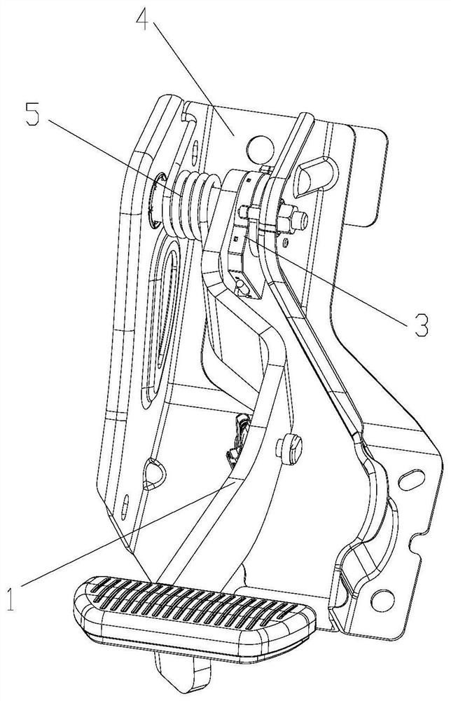
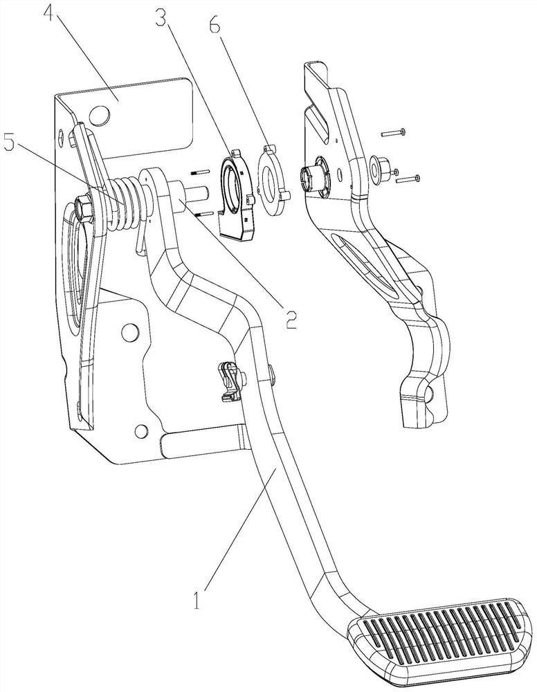
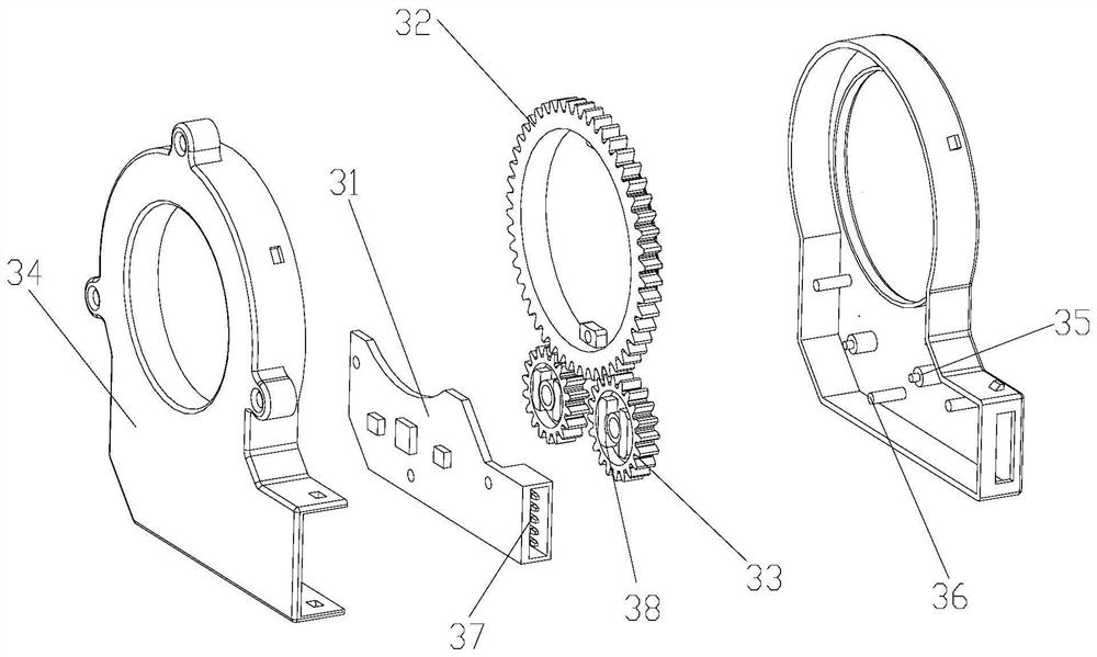
[0030] The present invention provides a brake pedal assembly, wherein the brake pedal assembly includes a pedal arm 1, a rotating shaft 2 connected to the pedal arm 1, and a brake light switch part 3, the brake light switch part 3 Including a circuit board 31, a rotating member connected to the rotating shaft 2, a magnet 38 arranged on the rotating member and a Hall chip arranged on the circuit board 31, the rotating shaft 2 can drive the rotating member Rotate to change the magnetic field formed by the magnet 38 , and the Hall chip can sense the change amount and change speed of the magnetic field.

[0031] The pedal arm 1 can pivot between a non-braking position and a braking po...


PUM


Abstract

The invention relates to the field of vehicle braking and discloses a brake pedal assembly and a vehicle. The brake pedal assembly comprises a pedal arm (1), a rotating shaft (2) connected to the pedal arm (1) and a brake lamp switch part (3). The brake lamp switch part (3) comprises a circuit board (31), a rotating piece, a magnet (38) and a Hall chip arranged on the circuit board (31). The rotating shaft (2) can drive the rotating piece to rotate so as to change a magnetic field formed by the magnet (38), and the Hall chip can sense a variable quantity and a variable speed of the magnetic field. According to the brake pedal assembly, a pivoting angle and a pivoting speed of the pedal arm are measured and reflected in a mode that the Hall chip is matched with the magnet, the position of the magnet corresponding to a new initial position of the pedal arm can be redefined even if the pedal arm is loosened and sinks, and a problem that a brake lamp switch cannot be normally turned off after the pedal arm is loosened is solved.

Description

technical field [0001] The invention relates to the technical field of vehicle braking, in particular to a brake pedal assembly and a vehicle. Background technique [0002] The brake light switch is installed on the brake pedal bracket. When the vehicle needs to decelerate, stop or emergency brake, the brake switch is turned on and off synchronously when the driver depresses the brake pedal. When the brake switch is turned on, the brake lights at the rear of the car are always on, especially when the car needs to brake at high speed, the brake lights can remind the rear vehicles to slow down in time and take necessary emergency measures. Prevent accidents from happening. [0003] Most of the brake light switches are mechanical switches, which are generally controlled by moving contacts and static contacts. The installation method is mostly screwed, and the brake light switch is installed on the bracket on the brake pedal. When the pedal is not depressed, the push rod of th...

Claims


Application Information

Patent Timeline
IPC IPC(8): B60T7/06B60Q1/44
CPCB60T7/06B60Q1/441
Inventor 蔡伟范志刚谢长浩徐荣昌王淑艳段福海
Owner GREAT WALL MOTOR CO LTD
Why Eureka
Try Eureka