
Cylindrical heating rod test section with chamber and parameter measurement method thereof

A test section, cylindrical technology, applied in the field of cylindrical heating rod test section and its parameter measurement, can solve the problems of complex structure, affecting the distribution of heating fluid flow and heat, and difficult measurement of test parameters, so as to avoid unnecessary Certainty, the effect of improving measurement accuracy

Active Publication Date: 2020-09-04
XI AN JIAOTONG UNIV
View PDF6 Cites 0 Cited by
  • Summary
  • Abstract
  • Description
  • Claims
  • Application Information

AI Technical Summary

Problems solved by technology

However, its structure is more complex than that of traditional cylindrical heating rods. The size of the inner and outer channels affects the flow rate of the heating fluid and the distribution of heat. It is inevitable to conduct research through thermal-hydraulic experiments.
The unique and complex structure of the cylindrical heating rod inside the tube brings difficulties to the measurement of test parameters
Based on this requirement, the present invention provides a cylindrical heating rod test section with a chamber and its parameter measurement method, the purpose of which is to solve the pressure and temperature measurement in the inner and outer channels of the cylindrical heating rod test section to study the circular heating rod test section. Problems of Heat Flow Distribution of Cylindrical Heating Rods

Method used


Image

  • Cylindrical heating rod test section with chamber and parameter measurement method thereof
  • Cylindrical heating rod test section with chamber and parameter measurement method thereof
  • Cylindrical heating rod test section with chamber and parameter measurement method thereof

Examples


Embodiment Construction

[0020] The present invention is described in detail below in conjunction with accompanying drawing:

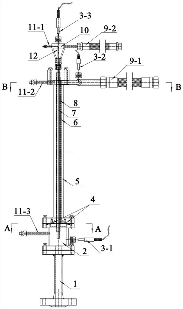
[0021] Such as figure 1 As shown, a cylindrical heating rod test section with a chamber, including a fully developed tube 1, a lower chamber 2, a test section outer casing 5 and an upper chamber 10 connected by flanges from bottom to top, is arranged in the test section. Cylindrical heating rod 8 in segment outer casing 5. The central circular channel of the cylindrical heating rod 8 is the inner channel 7 , and the annular channel between the outer casing 5 of the test section and the cylindrical heating rod 8 is the outer channel 6 .

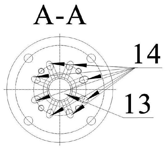
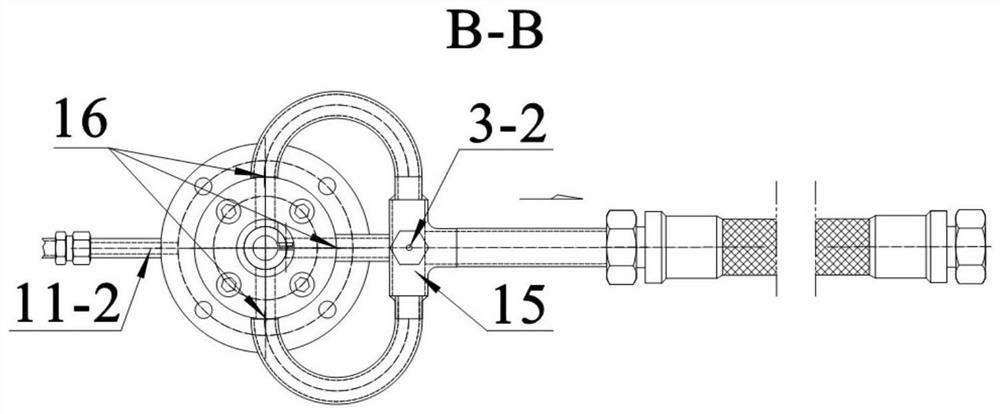
[0022] Such as figure 2 As shown, the lower chamber 2 is provided with a lower chamber pressure-taking channel 11-3 and a lower chamber thermal resistance 3-1, the lower end is connected to the fully developed tube 1, and the center of the upper end is provided with an inner hole 13 connected to the entrance of the inner passage 7, A numbe...


PUM


Abstract

The invention relates to a cylindrical heating rod test section with a chamber and a parameter measurement method thereof. The test section comprises a full development pipe, a lower chamber, a test section outer sleeve, an upper chamber and a cylindrical heating rod arranged in the test section outer sleeve, wherein the full development pipe, the lower chamber, the test section outer sleeve and the upper chamber are sequentially connected by flanges. The pressure tapping channels and the thermal resistors arranged in the lower chamber and the upper chamber can be used for measuring the pressure and temperature of cooling water at the inlet and the outlet of the inner channel. A pressure tapping channel and three water outlets which are uniformly distributed at an angle of 90 degrees are formed in the side edge of the upper flange of the test section outer sleeve, and the water outlets are connected with a pipeline and converged in the outer channel chamber. The pressure and temperature of cooling water at the outlet of the outer channel are measured through the test section outer sleeve pressure tapping channel and a thermal resistor arranged in the outer channel chamber. The testsection can simulate heating of the cylindrical heating rod and accurately and reasonably measure fluid parameters of the inner channel and the outer channel; the difficulty caused by a special innerchannel structure and a special outer channel structure of the cylindrical heating rod is solved; and meanwhile, uncertainty caused by large radial temperature gradient to measurement is avoided, andtherefore the measurement accuracy is improved.

Description

technical field [0001] The invention belongs to the technical field of industrial heating, and relates to a cylindrical heating rod test section with a chamber and a parameter measuring method thereof. [0002] technical background [0003] The cylindrical heating rod has the characteristics of double-sided heating, and the full contact with the large area of ​​the heating fluid can increase the heating power density by 20% to 50% on the premise of maintaining the existing temperature safety margin. Therefore, the cylindrical heating rod is A very safe and economical form of heating. However, its structure is more complex than that of traditional cylindrical heating rods. The size of the inner and outer channels affects the flow rate of the heating fluid and the distribution of heat. It is inevitable to study through thermal-hydraulic experiments. However, the unique and complex structure of the cylindrical heating rod inside the tube brings difficulties to the measurement o...

Claims


Application Information

Patent Timeline
Patent Type & Authority Applications(China)
IPC IPC(8): G01D21/02G01M10/00
CPCG01D21/02G01M10/00
Inventor 巫英伟姚灏章静秋穗正田文喜苏光辉
Owner XI AN JIAOTONG UNIV
Learn More