Rectangular steel pipe bending equipment

A rectangular steel pipe and equipment technology, applied in the field of rectangular steel pipe bending equipment, can solve problems such as the difficulty of accurately controlling the bending angle of steel pipes, and achieve the effect of automatic and efficient bending and precise control of the bending angle

Active Publication Date: 2020-09-11
郓城鸿源专用车有限公司
View PDF6 Cites 7 Cited by
  • Summary
  • Abstract
  • Description
  • Claims
  • Application Information

AI Technical Summary

Problems solved by technology

[0006] In order to overcome the shortcomings of the prior art that it is difficult to accurately control the bending angle of the steel pipe and that manual tools are required for bending, the technical problem to be solved by the present invention is to provide a method that can precisely control the bending angle and can automatically Rectangular steel pipe bending equipment for efficiently bending steel pipes

Method used


Image

  • Rectangular steel pipe bending equipment
  • Rectangular steel pipe bending equipment
  • Rectangular steel pipe bending equipment

Examples


Embodiment 1

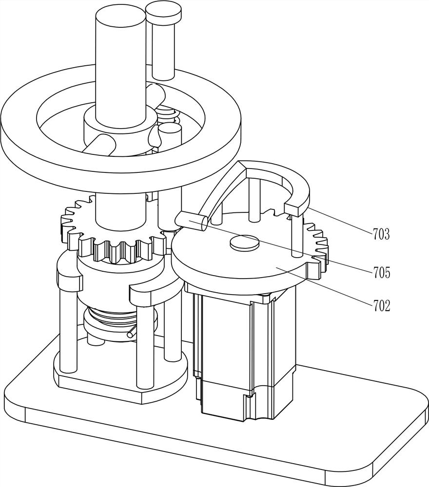
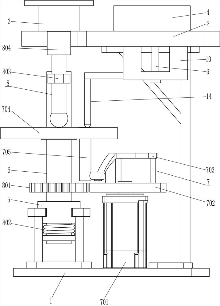
[0024] A rectangular steel pipe bending equipment, such as Figure 1-4 As shown, it includes a bottom plate 1, a workbench 2, a fixed block 3, a guide plate 4, a support sleeve 5, a rotating shaft 6, a lifting assembly 7, a rotating assembly 8, a sliding rod 9 and an N-shaped limit block 10. The top of the bottom plate 1 is provided with There is a workbench 2, a fixed block 3 is provided on the left side of the top of the workbench 2, a guide plate 4 is provided on the right side of the top of the workbench 2, a support sleeve 5 is provided on the left side of the bottom plate 1, and a rotating shaft 6 is provided in the support sleeve 5 , the rotating shaft 6 is provided with a lifting assembly 7 and a rotating assembly 8, the bottom of the right side of the workbench 2 is provided with a slide bar 9, the slide bar 9 is slidably provided with an N-shaped limit block 10, and the front side of the workbench 2 is provided with two Square groove 1001, the square groove 1001 is l...

Embodiment 2

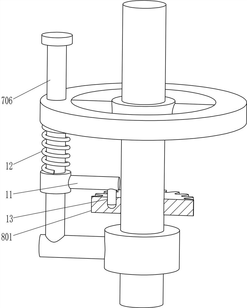
[0031] On the basis of Example 1, such as Figure 1-2 and Figure 4 As shown, it also includes a clamping rod 11 and a first spring 12. The guide rod 706 is provided with a clamping rod 11. The guide rod 706 is covered with a first spring 12. The upper end of the first spring 12 is connected to the bottom of the contact ring 704. The first The lower end of the spring 12 is connected to the top of the clamping rod 11 , the first gear 801 is provided with a clamping slot 13 , and the clamping rod 11 is matched with the clamping slot 13 .

[0032] It also includes a contact frame 14 , the left part of the N-type limiting block 10 is fixedly connected with the contact frame 14 , and the bottom of the contact frame 14 is in contact with the top of the contact ring 704 .

[0033]In the initial state, the clamping rod 11 cooperates with the clamping groove 13 so that the first gear 801 does not rotate, and when the contact ring 704 moves upwards, the clamping rod 11 is pulled upward...


PUM


Abstract

The invention relates to bending equipment, in particular to rectangular steel pipe bending equipment. The technical problem needing to be solved by the invention is to provide rectangular steel pipebending equipment which can precisely control the bending angle and can automatically and efficiently bend a steel pipe. The rectangular steel pipe bending equipment comprises a bottom plate which isin a cuboid shape, a workbench arranged at the top of the bottom plate, a fixing block arranged on one side of the top of the workbench, and a guide plate arranged on the side, away from the fixing block, of the top of the workbench. The rectangular steel pipe bending equipment achieves the effects of being capable of precisely controlling the bending angle, and automatically and efficiently bending a steel pipe, a quarter of the circle of a tooth lacking gear is provided with teeth, thus, a first gear and a rotary shaft can rotate only 90 degrees, a supporting block and a pressing rod can bend the rectangular steel pipe only 90 degrees, and the bending angle of the steel pipe can be effectively controlled.

Description

technical field [0001] The invention relates to a bending device, in particular to a rectangular steel pipe bending device. Background technique [0002] Steel pipe is a long strip of steel with a hollow center. According to the cross-sectional shape, it can be divided into circular, square and rectangular, etc., and rectangular steel pipes are generally long strips after production, and sometimes they need to be bent to a certain extent. At present, steel pipe bending is usually done manually using bending tools, or using a steel pipe bending machine to automatically bend steel pipes. However, manual bending with tools is time-consuming and laborious, and the quality is not good. good. [0003] Existing steel pipe bending machine, such as the patent announcement number is that the Chinese patent of CN204208955U discloses a kind of steel pipe bending machine, comprises base, is provided with cylinder on the base, is provided with gear at the end of cylinder, and gear and ra...

Claims


Application Information

Patent Timeline
Patent Type & Authority Applications(China)
IPC IPC(8): B21D7/024B21D43/00
CPCB21D7/024B21D43/003
Inventor 江青青
Owner 郓城鸿源专用车有限公司
Why Eureka
Try Eureka