Combination valve for oil pump

A combined valve and oil pump technology, applied in the direction of lubricating oil control valve, valve details, valve device, etc., can solve the problems of affecting the service life of parts, flowing to the inside of the car, the valve core deviates from the oil drain hole, etc., and achieves the protection of service life. Effect

Active Publication Date: 2020-09-11
嘉兴宏欣汽车零部件有限公司
View PDF9 Cites 0 Cited by
  • Summary
  • Abstract
  • Description
  • Claims
  • Application Information

AI Technical Summary

Problems solved by technology

[0002] The oil pump is used to ensure the circulation of lubricating oil in the lubrication system, and to provide a sufficient amount of lubricating oil at each speed of the engine to maintain sufficient lubricating oil pressure and ensure the lubrication of the engine. In order to prevent excessive oil pressure, It is usually necessary to set a pressure relief valve for pressure relief, but there are some impurities in the oil. These impurities enter the valve and adhere to the surface of the valve core, which will cause the valve core to not close tightly and affect the normal operation of the pressure relief valve, and these impurities will adhere to the valve core. On the inner wall, because the valve body is not easy to disassemble, these impurities cannot be removed from the inner wall of the valve, which will affect the use of the valve body for a long time. The core is in contact with engine oil for a long time, and the oil has a certain viscosity, which will cause the contact surface between the valve core and the oil drain hole to be bonded by engine oil, resulting in a decrease in the sensitivity when it is opened, and the valve core may deviate from the oil drain due to long-term use. hole, so we propose a combination valve for oil pump to solve this kind of problem

Method used


Image

  • Combination valve for oil pump
  • Combination valve for oil pump
  • Combination valve for oil pump

Examples


Embodiment Construction

[0024] The following will clearly and completely describe the technical solutions in the embodiments of the present invention with reference to the accompanying drawings in the embodiments of the present invention. Obviously, the described embodiments are only some of the embodiments of the present invention, not all of them.

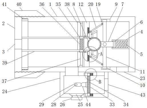
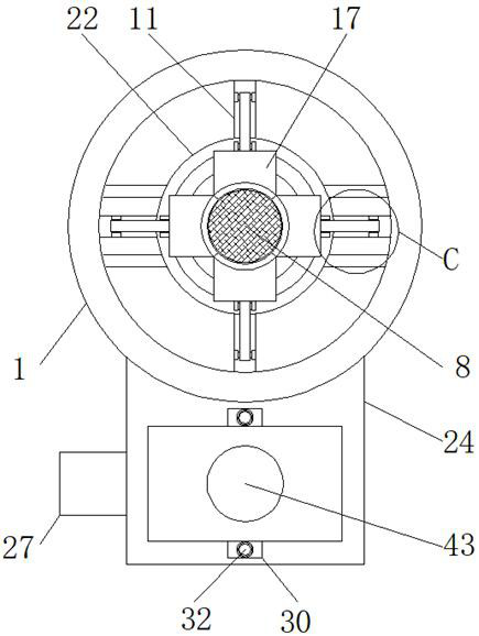
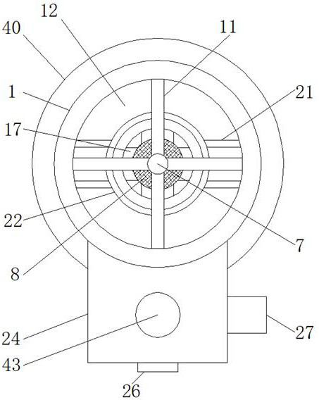
[0025] refer to Figure 1-7 , a combination valve for an oil pump, comprising a valve body 1, the left end of the valve body 1 is threadedly connected with a cover plate 2, the outer side of the cover plate 2 is fixedly fitted with an annular wing plate 40, and the inner side of the annular wing plate 40 is threaded with the valve body 1 Connected, the airtightness of the joint between the cover plate 2 and the valve body 1 can be strengthened through the annular wing plate 40 to avoid oil leakage.

[0026] The outside of the cover plate 2 is surrounded by a gasket 41, which strengthens the airtightness of the joint between the cover plate 2 and the valve...


PUM


Abstract

The invention relates to the technical field of combination valves, in particular to a combination valve for an oil pump. The combination valve comprises a valve body, wherein the left end of the valve body is in threaded connection with a cover plate, and an oil inlet hole is formed in the middle of the left side of the cover plate. According to the combination valve for the oil pump, the structure is simple, impurities in machine oil can be filtered to avoid the situation that the impurities flow into an automobile along with the machine oil to wear parts, and meanwhile, the situation that the impurities are attached to a spherical valve element to influence the leakproofness of the spherical valve element is avoided, a filter screen is convenient to clear, the machine oil accumulated onstop blocks can be cleared and scraped while pressure relief is carried out, rapid return of the spherical valve element and the stop blocks can be achieved through the acting force released by a first spring and a second spring, and a limiting rod is limited from four directions through four connecting rods so that the situation that the limiting rod deviates can be effectively avoided, the situation that the spherical valve element deviates is effectively avoided, the combination valve is convenient to disassemble, disassembling and clearing of the inner wall of a valve body can be carriedout at the same time, and the combination valve is worthy of popularization and application.

Description

technical field [0001] The invention relates to the technical field of combined valves, in particular to a combined valve for an oil pump. Background technique [0002] The oil pump is used to ensure the circulation of lubricating oil in the lubrication system, and to provide a sufficient amount of lubricating oil at each speed of the engine to maintain sufficient lubricating oil pressure and ensure the lubrication of the engine. In order to prevent excessive oil pressure, It is usually necessary to set a pressure relief valve for pressure relief, but there are some impurities in the oil. These impurities enter the valve and adhere to the surface of the valve core, which will cause the valve core to not close tightly and affect the normal operation of the pressure relief valve, and these impurities will adhere to the valve core. On the inner wall, because the valve body is not easy to disassemble, these impurities cannot be removed from the inner wall of the valve, which wil...

Claims


Application Information

Patent Timeline
Patent Type & Authority Applications(China)
IPC IPC(8): F01M1/16F01M11/03F16N23/00F16K27/08B08B9/043B01D29/03B01D29/50B01D35/02F01M1/02
CPCF01M1/16F01M11/03F16N23/00F16K27/08B08B9/0436B01D29/03B01D29/50B01D35/02F01M1/02
Inventor 沈灿
Owner 嘉兴宏欣汽车零部件有限公司
Why Eureka
Try Eureka