Vibration table control method and device

A control method and control device technology, which is applied in the direction of measuring device, vibration test, machine/structural component test, etc., can solve the problems of impact of moving parts, inability to accurately control the vibration of the moving coil 2, off-center position, etc., to achieve convenient and accurate The effect of control

Inactive Publication Date: 2020-09-11
SUZHOU SUSHI TESTING INSTR CO LTD
View PDF5 Cites 1 Cited by
  • Summary
  • Abstract
  • Description
  • Claims
  • Application Information

AI Technical Summary

Problems solved by technology

In addition, it may cause the moving parts in the driving device to be impacted. When this impact cannot be balanced in time, the moving coil will deviate from the center position until the equipment protection is triggered. Experimental vibration test
[0003] When an aircraft is flying at high altitude, it is usually in a relatively low-pressure environment. When the aircraft is parked at an airport on the ground, it is usually in a relatively high-pressure environment. When taking off or landing, the air pressure of the environment where the aircraft is located usually changes greatly. And fast, therefore, when performing vibration tests on aircraft and its related components, it is necessary to put the aircraft, related components and vibration table into a confined space, and quickly adjust the air pressure in the confined space, it is understandable that , which causes a sudden change in the thrust force on the moving coil 2, resulting in the inability to precisely control the vibration of the moving coil 2

Method used


Image

  • Vibration table control method and device
  • Vibration table control method and device
  • Vibration table control method and device

Examples


Embodiment Construction

[0019] The present invention will be described in detail below with reference to the embodiments shown in the accompanying drawings. However, this embodiment does not limit the present invention, and any structural, method, or functional changes made by those skilled in the art according to this embodiment are included in the protection scope of the present invention.

[0020] The following description and the accompanying drawings sufficiently illustrate specific embodiments herein to enable those skilled in the art to practice them. Portions and features of some embodiments may be included in or substituted for those of other embodiments. The scope of the embodiments herein includes the full scope of the claims, and all available equivalents of the claims. Herein, the terms "first", "second", etc. are only used to distinguish one element from another element without requiring or implying any actual relationship or order between these elements. In fact the first element can...


PUM


Abstract

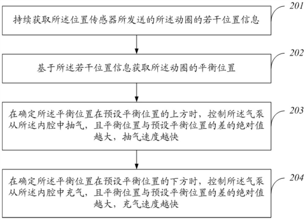
The invention discloses a vibration table control method and device. The control method comprises the following steps that a plurality of pieces of position information, sent by a position sensor, ofa moving coil are continuously obtained; the center position of the moving coil is acquired based on the plurality of pieces of position information; when it is determined that the center position islocated above a preset center position, an air pump is controlled to pump air from an inner cavity, and the larger the absolute value of the difference between the center position and the preset center position is, the higher the air pumping speed is; and when it is determined that the center position is located below the preset center position, the air pump is controlled to inflate air from the inner cavity, and the larger the absolute value of the difference between the center position and the preset center position is, the higher the inflation speed is. Therefore, the change of the air pressure of the surrounding environment can be adapted, and the vibration of the moving coil can be accurately controlled.

Description

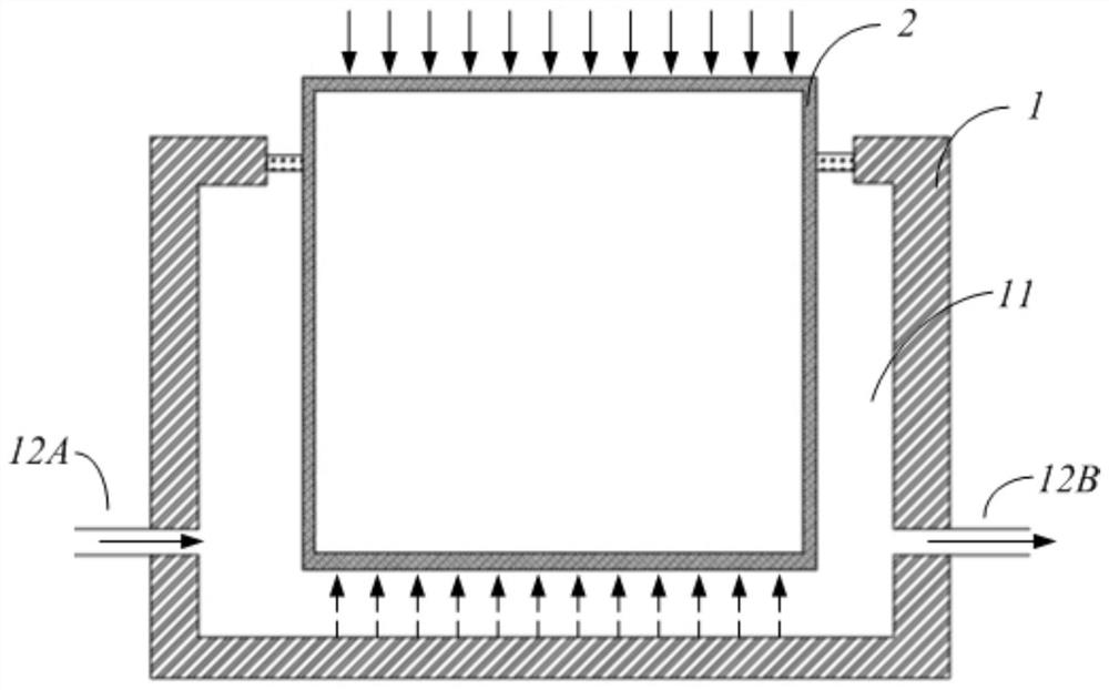
technical field [0001] The invention relates to the technical field of mechanical environment test equipment, in particular to a control method and device for a vibrating table. Background technique [0002] The vibration table can simulate various environmental vibrations encountered by products in manufacturing, assembly, transportation and use, and is used to evaluate whether the product can withstand environmental vibrations. Its structure is usually as follows: figure 1 As shown, it includes: a pressure-bearing table body 1 with an inner cavity 11 , a moving coil 2 arranged in the inner cavity 11 and a driving device, which can drive and adjust the vibration of the moving coil 2 . In addition, air is usually used to flow through the inner cavity 11. It can be understood that the upper end surface of the inner ring 2 is subjected to the downward pressure of the air in the surrounding environment (as shown by the solid arrow in the figure), and the lower end surface is su...

Claims


Application Information

Patent Timeline
Patent Type & Authority Applications(China)
IPC IPC(8): G01M7/02B64F5/60
CPCB64F5/60G01M7/022
Inventor 姜健张雷雷朱江峰
Owner SUZHOU SUSHI TESTING INSTR CO LTD
Why Eureka
Try Eureka