Supercharge Your Innovation With Domain-Expert AI Agents!

Video cassette recorders

A video recorder and connection mechanism technology, applied in data recording, image communication, recording information storage, etc.

Inactive Publication Date: 2003-07-30
THOMSON MULTIMEDIA SA
View PDF0 Cites 0 Cited by
  • Summary
  • Abstract
  • Description
  • Claims
  • Application Information

AI Technical Summary

Problems solved by technology

[0003] In the case of a VCR permanently connected to a decoder and TV, the TV may be on when the VCR and decoder are in standby mode

Method used


Image

  • Video cassette recorders
  • Video cassette recorders
  • Video cassette recorders

Examples


Embodiment Construction

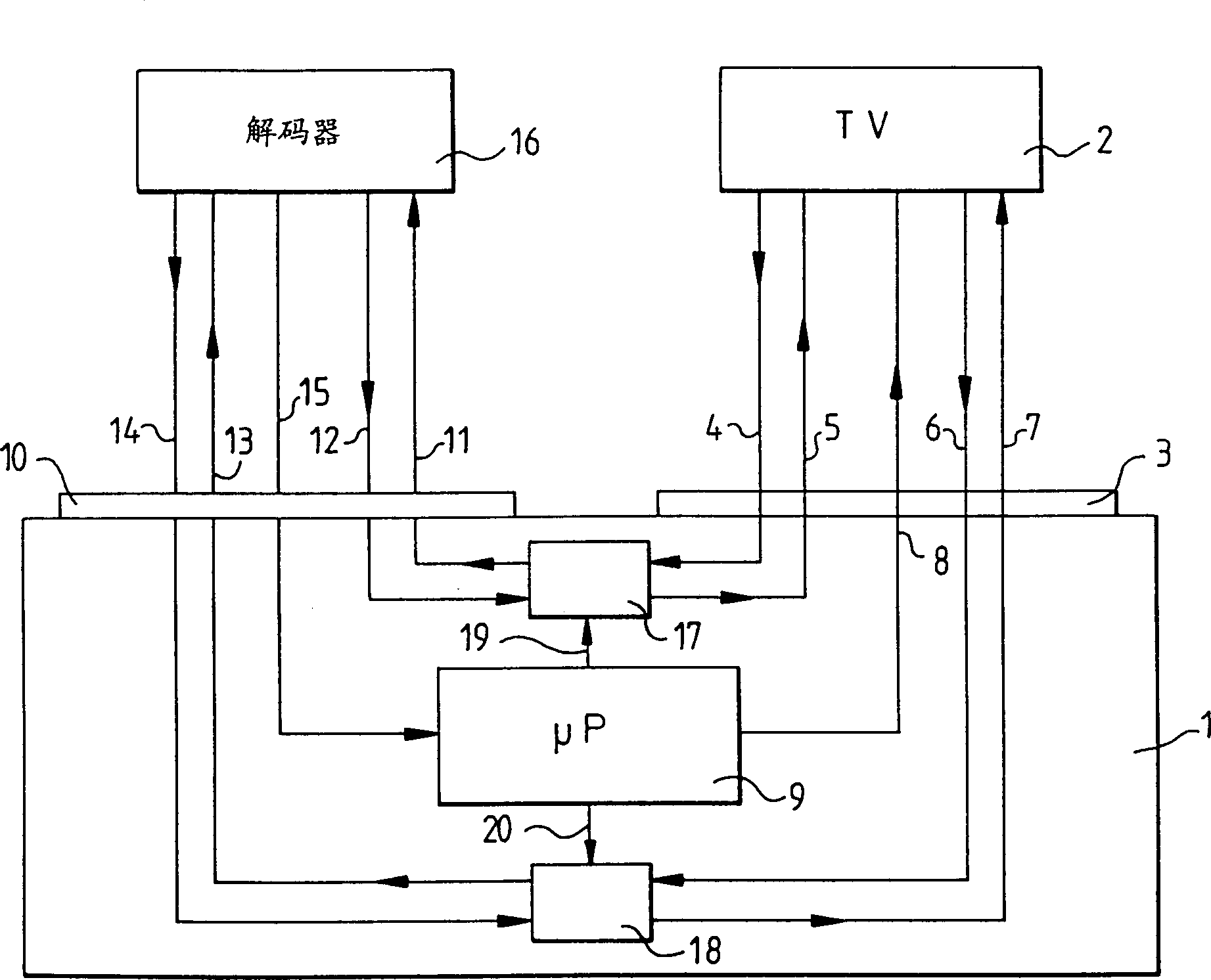
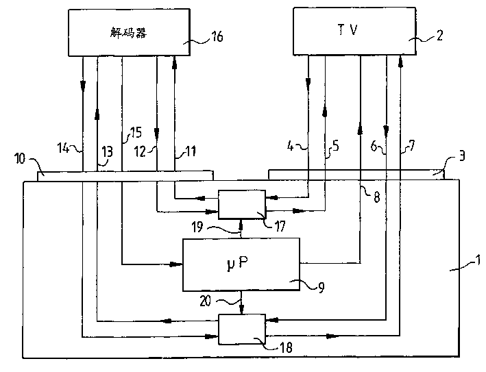
[0010] figure 1 Indicates VCR1. In this VCR, only circuits useful for understanding the invention are shown schematically. The VCR1 is connected to the television receiver 2 through the first connecting mechanism scart3, and is connected to the decoder 16 through the second connecting mechanism scart10. Such scarts are well known in the art. They include a plurality of pins or terminals, each having a known function. To understand the invention, only five of those terminals are considered. VCR 1 includes a microprocessor 9 which controls video switch 17 and audio switch 18 via control lines 19 and 20, respectively. The first terminal 4 of scart3 is used to receive the video signal from TV2. When the switch 17 is turned on, the video signal can be sent to the decoder through the switch 17 and the first pin 11 of the scart10. Similarly, an unscrambled video signal can be transmitted from the second pin 12 of scart10 to the second pin 5 of scart3 via switch 17 . The third ...


PUM


Abstract

VCR connectable to a television receiver and a decoder of scrambled signal in which means are foreseen so that in a first stand-by mode of the VCR called ECO1 mode, if no scrambled signal is received by the television receiver only the video signal is routed to the decoder through the VCR, and if a scrambled signal is received then also the audio signal is routed through the VCR. Due to the savings in power by switching off the audio signal, ECO1 mode consumption is about 3W.

Description

technical field [0001] This invention relates to video cassette recorders (VCRs). Background technique [0002] In all electronic devices, efforts are made to reduce power consumption, especially when the device is in a so-called standby mode. The standby mode is a mode in which the device is turned off except for a receiving circuit for receiving an infrared reset signal from, for example, a remote controller. [0003] In the case of a VCR permanently connected to a decoder and TV, the TV may be on when the VCR and decoder are in standby mode. This state will continue until the user switches to a channel to which the video signal is scrambled. If the user switches to a scrambled channel, the decoder must be switched on. Changes made at the decoder level are passed through the VCR in standby mode. More precisely, the video signal is input from the TV to the VCR through the first pin of the first connection mechanism, and then input from the VCR to the decoder through the...

Claims


Application Information

Patent Timeline
IPC IPC(8): H04N5/765H04N5/775H04N5/781H04N5/7826
CPCH04N5/775
Inventor 弗兰克·杜蒙陈志南
Owner THOMSON MULTIMEDIA SA
Features
  • R&D
  • Intellectual Property
  • Life Sciences
  • Materials
  • Tech Scout
  • Unparalleled Data Quality
  • Higher Quality Content
  • 60% Fewer Hallucinations
Learn More