Discharging device for iron sheet bending

A technology of blanking and iron sheet, applied in the direction of feeding device, positioning device, storage device, etc., can solve the problems of high safety risk, energy consumption, etc., and achieve safe use of equipment, faster bending speed, safe and convenient use of equipment Effect

Active Publication Date: 2020-09-18
青岛华胜万兴工贸有限公司
View PDF8 Cites 3 Cited by
  • Summary
  • Abstract
  • Description
  • Claims
  • Application Information

AI Technical Summary

Problems solved by technology

[0003] At present, when bending the iron sheet, first, the iron sheet to be bent needs to be placed on the placing part of the bending device, and then the iron sheet is bent through a cylinder that moves up and down. Finally, the ring-shaped iron piece will be set on the bent cylinder. At this time, the ring set on the cylinder needs to be removed. In this way, when placing the iron piece for bending, people need to watch the time to prevent falling. At the same time, when the cylinder moves to the top, the iron ring on the cylinder needs to be removed. In this way, there is a great safety risk and it consumes a lot of energy

Method used


Image

  • Discharging device for iron sheet bending
  • Discharging device for iron sheet bending
  • Discharging device for iron sheet bending

Examples


Embodiment 1

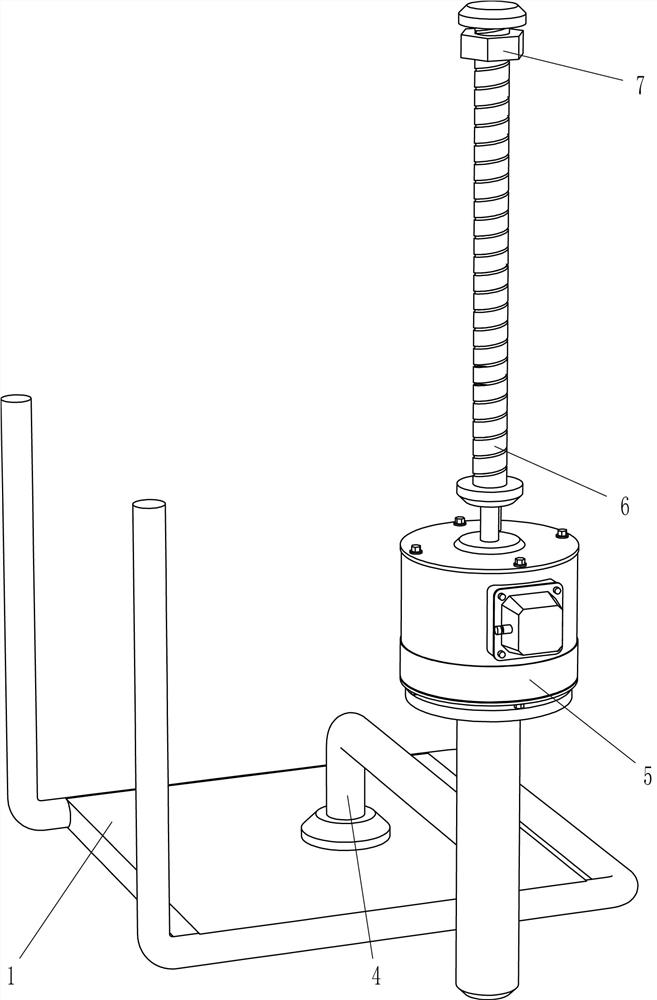
[0021] A blanking device for bending iron sheets, such as Figure 1-4 As shown, it includes a frame 1, a material discharging assembly, a lifting assembly and a pushing assembly. The top of the left side of the frame 1 is provided with a material discharging assembly for discharging by lifting, and the front side of the top of the frame 1 is equipped with a The working lifting component is provided with a pushing component between the lifting component and the discharging component through lifting.

[0022] like figure 1 and 2 As shown, the discharging assembly includes a guide rail 2 and a blanking frame 3, the top left side of the frame 1 is fixed with the guide rail 2 by bolts, and the top right side of the guide rail 2 is fixed with the blanking frame 3 by bolts.

[0023] like figure 1 and 3 As shown, the lifting assembly includes a support rod 4, a reduction motor 5, a screw rod 6 and a nut 7, the front middle part of the frame 1 is connected with a support rod 4 by a...

Embodiment 2

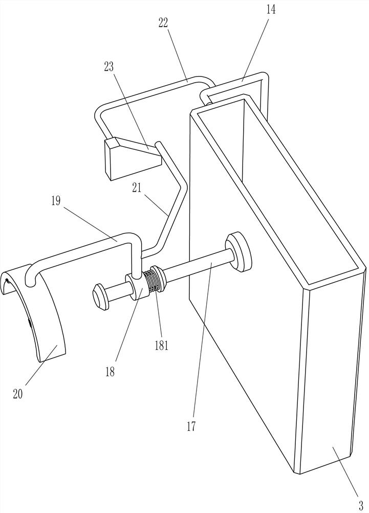
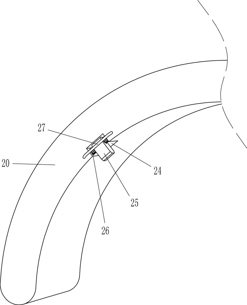
[0030] On the basis of Example 1, such as figure 1 , 5 Shown in and 6, also include fixed rod 17, sliding sleeve 18, second spring 181, second special-shaped rod 19, arc plate 20, pull bar 21, U-shaped bar 22, wedge block 23, block 25, torsion spring 26 and retaining bar 27, blanking frame 3 left side tops are welded with fixed bar 17, and fixed bar 17 left part sliding type is provided with sliding sleeve 18, is connected with second spring 181 between the fixed bar 17 middle part and sliding sleeve 18 right sides , the top of the sliding sleeve 18 is welded with a second special-shaped rod 19, the left end of the second special-shaped rod 19 is welded with an arc-shaped plate 20, the right part of the second special-shaped rod 19 is welded with a tie rod 21, and the upper part of the first special-shaped rod 14 on the rear side is welded with a U Type bar 22, U-shaped bar 22 front ends are welded with wedge-shaped block 23, and wedge-shaped block 23 cooperates with pull bar...


PUM


Abstract

The invention relates to a discharging device, in particular to a discharging device for iron sheet bending. According to the discharging device for iron sheet bending, the operation is safe, and using is easy. The discharging device for iron sheet bending comprises a rack, a discharging assembly, a lifting assembly and a pushing assembly; the discharging assembly is installed on the rack and usedfor discharging materials in a lifting mode; the lifting assembly is installed on the rack and is powered by a motor to work; and the pushing assembly is installed between the lifting assembly and the discharging assembly and is used for pushing in a lifting mode. According to the discharging device for iron sheet bending, through cooperation of the discharging assembly and the pushing assembly,iron sheets can be continuously pushed in, the bending speed of the iron sheets is increased, the gear motor can automatically push the iron sheets in for bending, and the equipment is very safe to use.

Description

technical field [0001] The invention relates to a blanking device, in particular to a blanking device for bending iron sheets. Background technique [0002] Bend: to bend, to bend, after bending. The term bending, in the professional atlas of steel bar engineering, indicates the radius of the steel bar after bending, which is called "bending radius". When making an iron ring, the iron sheet needs to be bent. [0003] At present, when bending the iron sheet, first, the iron sheet to be bent needs to be placed on the placing part of the bending device, and then the iron sheet is bent through a cylinder that moves up and down. Finally, the ring-shaped iron piece will be set on the bent cylinder. At this time, the ring set on the cylinder needs to be removed. In this way, when placing the iron piece for bending, people need to watch the time to prevent falling. At the same time, when the cylinder moves to the top, the iron ring on the cylinder needs to be removed. In this way...

Claims


Application Information

Patent Timeline
IPC IPC(8): B21D43/13B21D45/02B21D5/00
CPCB21D43/13B21D45/02B21D5/00
Inventor 高贤娣
Owner 青岛华胜万兴工贸有限公司
Why Eureka
Try Eureka