Glass tube sealing device for medical glass tube sealing assembly machine

A technology of medicinal glass and sealing device, which is applied in the direction of closure, application, and packaging with stoppers, and can solve the problems of sticking and sealing parts that are easy to adhere to dust, etc.

Active Publication Date: 2020-09-29
山东鑫诺新玻璃工程有限公司
View PDF9 Cites 4 Cited by
  • Summary
  • Abstract
  • Description
  • Claims
  • Application Information

AI Technical Summary

Benefits of technology

This patented technology allows for precise placement of an optical fiber during manufacturing processes such as welding. By placing a special device called a glass pipe onto one part of the process (the location where it needs to connect) beforehand, there will be less chance any contamination particles get inside when connecting parts together due to their close proximity between them. Additionally, this design prevents damage caused by external factors like vibrations or impacts. Overall, these technical improvements improve the efficiency and reliability of the production line's equipment.

Problems solved by technology

This patented technical problem addressed in this patents relates to improving the quality control for manufacturing or handling glass materials during their use in different applications like pharmaceuticals, food products, electronics, healthcare, defense systems, and others due to the lacking of suitable methods that prevent contamination caused by external factors like airborne particles, moisture condensations, heat shocks, and acids while maintaining opaque characteristics at temperatures ranging between 0-370 degrees Celsius.

Method used


Image

  • Glass tube sealing device for medical glass tube sealing assembly machine
  • Glass tube sealing device for medical glass tube sealing assembly machine
  • Glass tube sealing device for medical glass tube sealing assembly machine

Examples


Embodiment 1

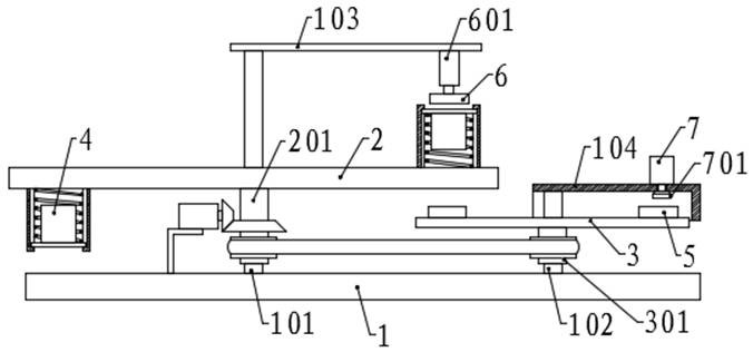
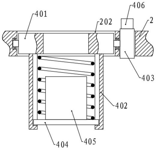
[0034]Please refer to the accompanying drawings, the present invention provides a technical solution: a glass tube sealing device for a pharmaceutical glass tube sealing assembly machine, including a base 1, a first fixed shaft 101 is fixed on the left side of the top surface of the base 1, and The right side of the face is fixed with a second fixed shaft 102, the first fixed shaft 101 is rotatably connected with a first rotating cylinder 201, the rotating cylinder on the second fixed shaft 102 is connected with a second rotating cylinder 301, and the first rotating cylinder 201 and the second rotating cylinder A driving assembly is arranged between the two rotating cylinders 301, the second rotating plate 3 is fixed on the top of the second rotating cylinder 301, the first rotating plate 2 is fixed on the top of the first rotating cylinder 201, and the first rotating plate 2 is fixed on the top of the first rotating cylinder 201. The right end of the plate 2 is positioned abov...

Embodiment 2

[0045] The structure of this embodiment is basically the same as that of Embodiment 1, the difference is that the top end of the second fixed shaft 102 protrudes from the second rotating plate 3 and is fixed with a second fixed plate 104, the top surface of the second fixed plate 104 is right The jet pump 7 is fixed on the side, and the nozzle 701 is fixed on the right side of the bottom surface, and the nozzle 701 is connected with the jet pump 7 .

[0046] When the first rotating plate 2 drives the sealing to fix the sealing position, the second roller 502 first contacts the first arc surface on the second cam 302, and the sealing piece is positioned through the clamping block 501 and the slot, and then rotates to the nozzle 701 At the top surface of the sealing part, the blowing pump 7 and the nozzle 701 are used to blow off the dust and debris that may exist on the sealing part, so as to improve the subsequent sealing quality; Sterilization lamps and other structures are a...


PUM


Abstract

The invention discloses a glass tube sealing device for a medical glass tube sealing assembly machine in the technical field of medical glass tube production and processing. The glass tube sealing device comprises a base, a first rotating plate, a second rotating plate, a first positioning assembly, a second positioning assembly and a driving assembly. According to the glass tube sealing device, the position of a glass tube is fixed through the first positioning assembly, the position of a sealing piece is adjusted and positioned through the action of the second positioning assembly and a second cam, a first roller moves along the wheel surface of a first cam, the first cam enables a rack to move, the first positioning assembly and the glass tube are driven to rotate, a tube opening rotates downwards, a pressing plate drives a sliding plate to move downwards, the tube opening of the glass tube is tightly pressed on the sealing piece, so that the sealing piece is tightly clamped on theglass tube, and sealing is completed; and one side, in contact with the glass tube opening, of the sealing piece is placed upwards and is not in contact with other structures, so that the sealing quality is prevented from being influenced by dust or other sundries and the like adhered to the sealing piece.

Description


Claims


Application Information

Patent Timeline
Owner 山东鑫诺新玻璃工程有限公司
Why Eureka
Try Eureka