Prying-resistant and shearing-resistant padlock

An anti-shear and anti-pry technology, applied in padlocks, building locks, buildings, etc., can solve problems such as prying and cutting

Inactive Publication Date: 2020-10-02
林文乙
View PDF6 Cites 0 Cited by
  • Summary
  • Abstract
  • Description
  • Claims
  • Application Information

AI Technical Summary

Problems solved by technology

[0002] Generally existing padlock A, see figure 1 As shown, the padlock A is mostly provided with an exposed shackle A0, and the shackle A0 is a locked component B, which is set as a buckle plate B1 with a hole B0 and buckled in a buckle hole B2 When the lock hook A0 locks the locked component B, it is easy to be pried open and cut off because the lock hook A0 is exposed; in view of the above-mentioned defects existing in the present invention, the inventor has devoted himself to research and improvement , so the invention was first created

Method used


Image

  • Prying-resistant and shearing-resistant padlock
  • Prying-resistant and shearing-resistant padlock
  • Prying-resistant and shearing-resistant padlock

Examples


Embodiment Construction

[0017] Relevant present invention is for reaching above-mentioned purpose of use and effect, the technical means that adopts, presents preferred feasible embodiment hereby, and cooperates as shown in the drawing, is described in detail as follows:

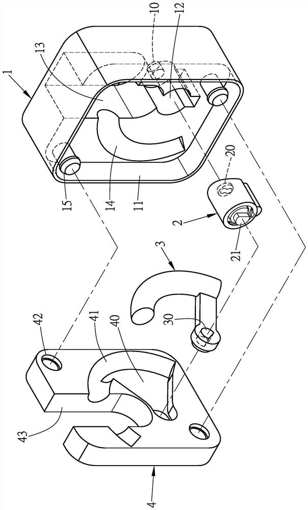
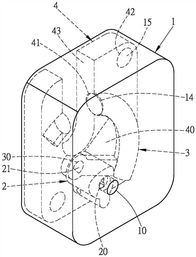
[0018] For an example of the invention, see figure 2 As shown, it is mainly composed of a housing 1, a lock core 2, a lock hook 3 and a bottom plate 4. One side of the housing 1 is provided with an insertion hole 10, and the other side of the housing 1 is provided with a chamber 11. The chamber 11 is provided with a lock core slot 12 , a lock slot 13 , a front lock hook path 14 and an engaging portion 15 , and the engaging portion 15 is used as a leg; the lock core 2 is assembled in the lock core slot 12 of the housing 1 , the front of the lock core 2 is provided with a lock hole 20, the rear of the lock core 2 is provided with a protruding shaft 21, and the protruding shaft 21 is set as a non-circular body; the lock hook 3 is ass...


PUM


Abstract

The invention provides a prying-resistant and shearing-resistant padlock which is provided with a housing, a lock cylinder, a latch hook and a bottom plate, wherein an insertion hole is formed in oneside of the housing, an accommodation chamber is arranged on the other side of the housing, the accommodation chamber is provided with a lock cylinder groove, a lock catch groove, a front latch hook channel and a joining part. The lock cylinder is arranged in the lock cylinder of the housing, a lock hole is formed in front of the lock cylinder, and a convex shaft is arranged behind the lock cylinder; the latch hook is arranged in the front latch hook channel of the housing, and a shaft hole is formed in the latch hook; the bottom plate is arranged in the accommodation chamber of the housing, amovable space, a back latch hook channel and an abutting part are arranged on one side of the bottom plate, and a latch hook port is formed in one end of the bottom plate. Thus, the latch hook port of the bottom plate and the lock catch groove of the housing a hung to a locked assembly and the lock cylinder drives the latch hook to lock the locked assembly to hide the latch hook by means of the housing, so that prying and shearing are prevented.

Description

technical field [0001] The invention relates to an anti-prying and anti-shearing padlock, which is specially provided with a housing, a lock core, a lock hook and a bottom plate. One side of the housing is provided with an insertion hole, and the other side of the housing is provided with a chamber. The chamber is provided with a lock core groove, a lock buckle groove, a front lock hook road and a joint part; There is a protruding shaft; the lock hook is set on the front lock hook road of the shell, and one end of the lock hook is provided with a shaft hole; the bottom plate is set in the housing chamber of the shell, and one side of the bottom plate is provided with an activity space , the rear lock hook road and the docking part, one end of the base plate is provided with a lock opening; in this way, the lock opening of the base plate and the lock groove of the housing are hung on the locked component, and then the lock core is used to drive the lock The locking hook locks ...

Claims


Application Information

Patent Timeline
Patent Type & Authority Applications(China)
IPC IPC(8): E05B67/02E05B67/28
CPCE05B67/02E05B67/28
Inventor 林文乙
Owner 林文乙
Why Eureka
Try Eureka