Supercharge Your Innovation With Domain-Expert AI Agents!

A positioning tool for processing circular mechanical parts

A technology for mechanical parts and positioning tooling, applied to workpiece clamping devices, manufacturing tools, etc., can solve problems such as poor precision and inconvenient use

Active Publication Date: 2021-08-20
抚顺飞鹤金属制品有限公司
View PDF0 Cites 0 Cited by
  • Summary
  • Abstract
  • Description
  • Claims
  • Application Information

AI Technical Summary

Problems solved by technology

[0003] The purpose of the present invention is to solve the problems of poor precision and inconvenient use in the prior art, and propose a positioning tool for processing circular mechanical parts

Method used


Image

  • A positioning tool for processing circular mechanical parts
  • A positioning tool for processing circular mechanical parts
  • A positioning tool for processing circular mechanical parts

Examples


Embodiment 1

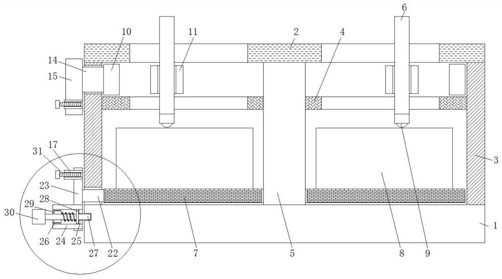
[0024] refer to Figure 1-4 , a positioning tool for processing circular mechanical parts, including a base 1, a worktable 2 is arranged vertically above the base 1, and a partition 4 and a central axis column are fixedly connected between the bottom side of the worktable 2 and the base 1 5. The central axis column 5 is located on the inner side of the support cylinder 3, and the inner wall of the support cylinder 3 is fixedly connected with a partition 4. Both the partition 4 and the work surface 2 are provided with sliding holes, and there are several sliding holes respectively, which are divergent. The positioning clamp rods 6 are slidably connected in the sliding holes, and the positioning clamp rods 6 are vertically arranged. The side is provided with a rotating ring plate 7, and the rotating ring plate 7 is rotatably covered on the outside of the cylinder of the central axis column 5, and the top side of the rotating ring plate 7 is fixedly connected with a fixed-height ...

Embodiment 2

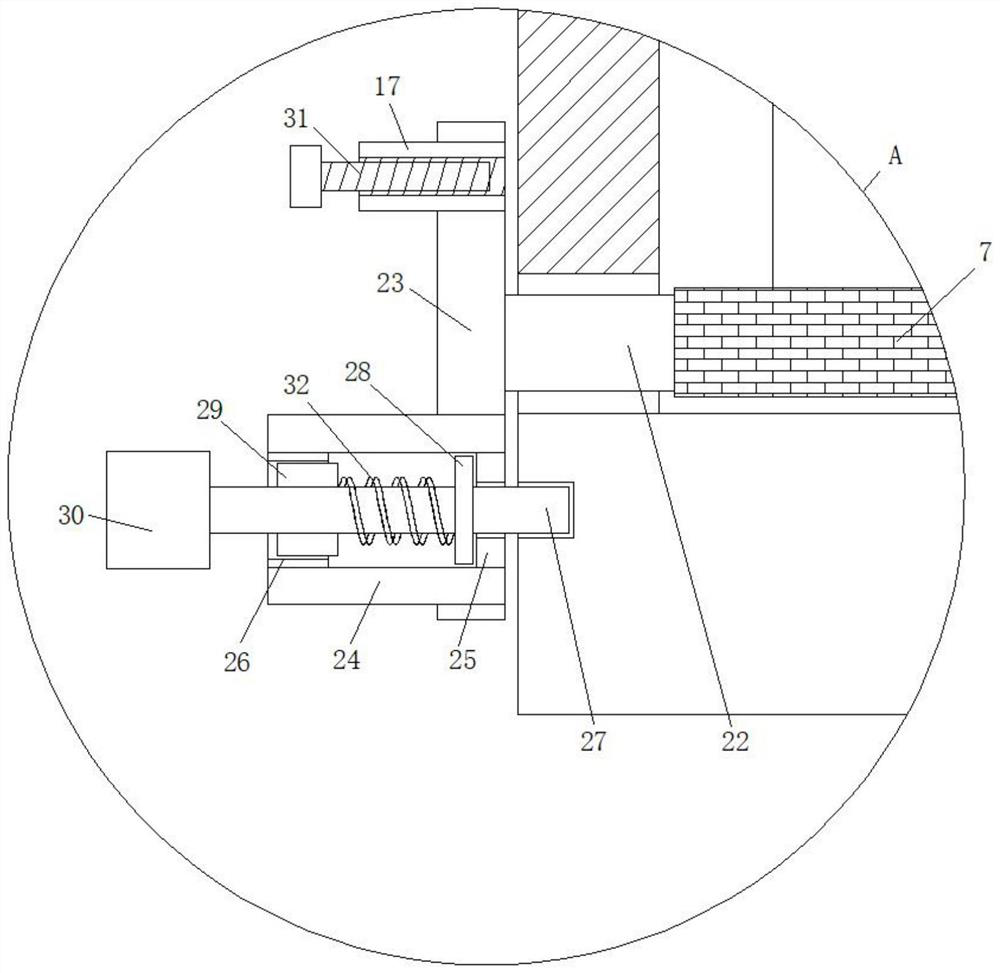
[0028] Such as Figure 1-4 As shown, this embodiment is basically the same as Embodiment 1. Preferably, the board bodies of outer control board one 15 and outer control board two 23 are provided with horizontal through holes two respectively and are fixedly connected with threaded barrel 17, and threaded barrel 17 is internally threaded. A locking bolt 31 is connected.

[0029] In this embodiment, the locking bolt 31 on the side of the outer control board 15 is used when the workbench not only needs to locate the circular mechanical parts, but also needs to fix them.

Embodiment 3

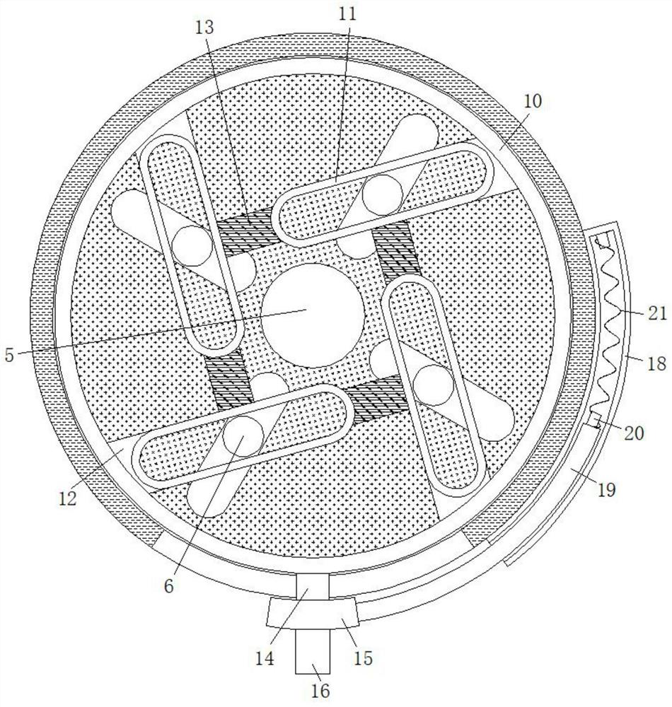
[0031] Such as Figure 1-4 As shown, this embodiment is basically the same as Embodiment 1. Preferably, the closed rail enclosures 11 are respectively arranged at an included angle relative to the sliding holes.

[0032] In this embodiment, the closed track coaming plate 11 can push the positioning clamp bar 6 to slide in the sliding hole when it is orbiting.


PUM


Abstract

The invention discloses a positioning tool for processing circular mechanical parts, comprising a base, a work table is arranged vertically above the base, and a partition plate and a central axis are fixedly connected between the bottom side of the work table and the base Column, the central axis column is located on the inner side of the support cylinder, the inner wall of the support cylinder is fixedly connected with a partition plate, the partition plate and the work table are both provided with sliding holes, and there are several sliding holes respectively and divergently. The sliding holes are respectively slidably connected with positioning clamp rods, the positioning clamp rods are arranged vertically, the bottom end of the positioning clamp rods extends to the bottom side of the partition plate and a universal ball is installed, and the base The top side of the rotating ring plate is provided with a rotating ring plate, the rotating cover of the rotating ring plate is outside the cylinder of the central axis column, and the top side of the rotating ring plate is fixedly connected with a fixed-height rail die seat. The invention is convenient to use, saves manpower, improves production efficiency, has strong applicability, and satisfies people's use requirements in production and life.

Description

technical field [0001] The invention relates to the technical field of machining equipment for mechanical parts, in particular to a positioning tool for machining circular mechanical parts. Background technique [0002] With the progress and development of society, the use of mechanical equipment has been widely used in various fields. In the process of assembling mechanical equipment, circular parts are one of the most common mechanical parts. In the process of parts production and deep processing, it is necessary to place the mechanical parts to be processed on the top of the worktable and center them. Therefore, people often draw multiple concentric circles on the top of the workbench or processing table, and The centering of circular mechanical parts is carried out by people's naked eyes. Now people can also realize this operation through the clamping rods that move synchronously. The top of the processing table brings restrictions to the subsequent finishing of circula...

Claims


Application Information

Patent Timeline
Patent Type & Authority Patents(China)
IPC IPC(8): B25B11/00
CPCB25B11/00
Inventor 赖剑峰张金新
Owner 抚顺飞鹤金属制品有限公司
Features
  • R&D
  • Intellectual Property
  • Life Sciences
  • Materials
  • Tech Scout
  • Unparalleled Data Quality
  • Higher Quality Content
  • 60% Fewer Hallucinations
Learn More