
Electronic equipment

An electronic equipment, electromagnetic technology, applied in the field of electronics, can solve the problem of poor sound effect of the receiver module

Active Publication Date: 2020-10-16
VIVO MOBILE COMM CO LTD
View PDF12 Cites 4 Cited by
  • Summary
  • Abstract
  • Description
  • Claims
  • Application Information

AI Technical Summary

Problems solved by technology

[0003] The purpose of the embodiment of the present application is to provide an electronic device that can solve the problem of poor sounding effect of the receiver module

Method used


Image

  • Electronic equipment
  • Electronic equipment
  • Electronic equipment

Examples


Embodiment Construction

[0015] The following will clearly and completely describe the technical solutions in the embodiments of the present application with reference to the drawings in the embodiments of the present application. Obviously, the described embodiments are part of the embodiments of the present application, not all of them. Based on the embodiments in this application, all other embodiments obtained by persons of ordinary skill in the art without creative efforts fall within the protection scope of this application.

[0016] The terms "first", "second" and the like in the specification and claims of the present application are used to distinguish similar objects, and are not used to describe a specific sequence or sequence. It is to be understood that the data so used are interchangeable under appropriate circumstances such that the embodiments of the application can be practiced in sequences other than those illustrated or described herein. In addition, "and / or" in the specification an...


PUM


Abstract

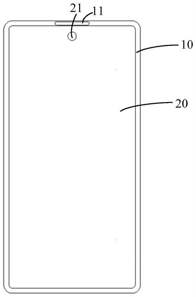
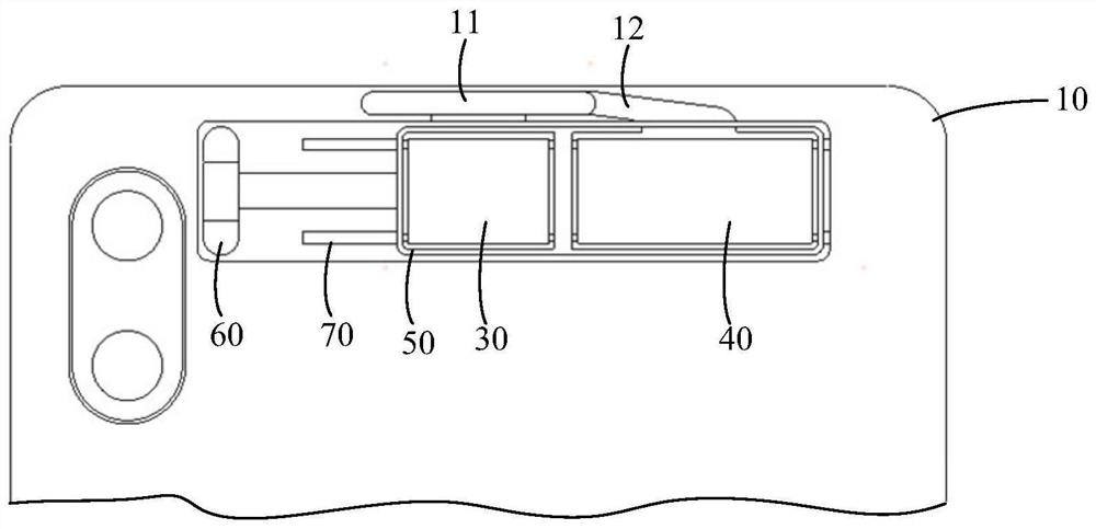
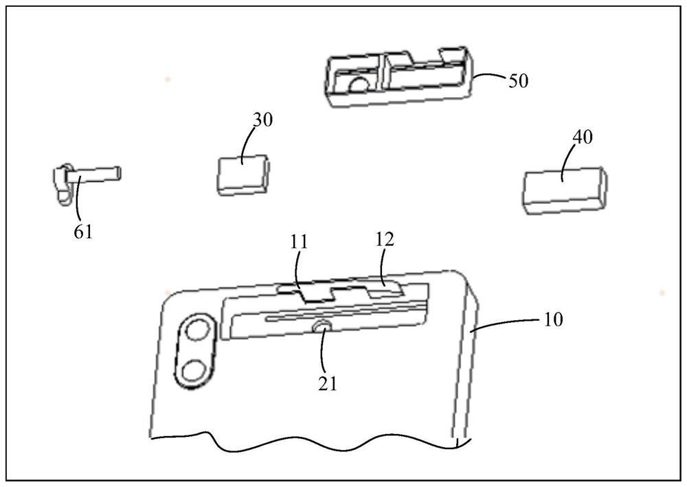
The invention discloses electronic equipment, and belongs to the technical field of electronics. The electronic equipment includes: a shell, a display module, a camera module and a receiver module, and the shell comprises a containing cavity. The display module is arranged in the containing cavity; the display module is provided with a first through hole for light to pass through, and the light passes through the first through hole and enters the camera module; the shell is provided with a first through hole which enables the receiver module to emit sound, the camera module and the receiver module are both movably arranged in the containing cavity, and the camera module is arranged facing the display module. Therefore, when the electronic equipment needs to produce sound through the receiver module, the receiver module can be controlled to move to the position opposite to the second through hole, and the distance between the receiver module and the second through hole is shortened, sothat the sound production effect of the receiver module is enhanced.

Description

technical field [0001] The present application belongs to the field of electronic technology, and in particular relates to an electronic device. Background technique [0002] With the development of electronic technology, people have higher and higher requirements on the screen-to-body ratio of electronic devices. In actual use, in order to ensure a high screen-to-body ratio of the electronic device, the distance between the receiver module of the electronic device and the corresponding receiver sound hole is relatively long, resulting in poor sounding effect of the receiver module. Contents of the invention [0003] The purpose of the embodiments of the present application is to provide an electronic device that can solve the problem of poor sound generation effect of the receiver module. [0004] In order to solve the above-mentioned technical problems, the application is implemented as follows: [0005] An embodiment of the present application provides an electronic d...

Claims


Application Information

Patent Timeline
Patent Type & Authority Applications(China)
IPC IPC(8): H04M1/03
CPCH04M1/03
Inventor 阳雪荣李乐乐陈俊辉
Owner VIVO MOBILE COMM CO LTD
Learn More