

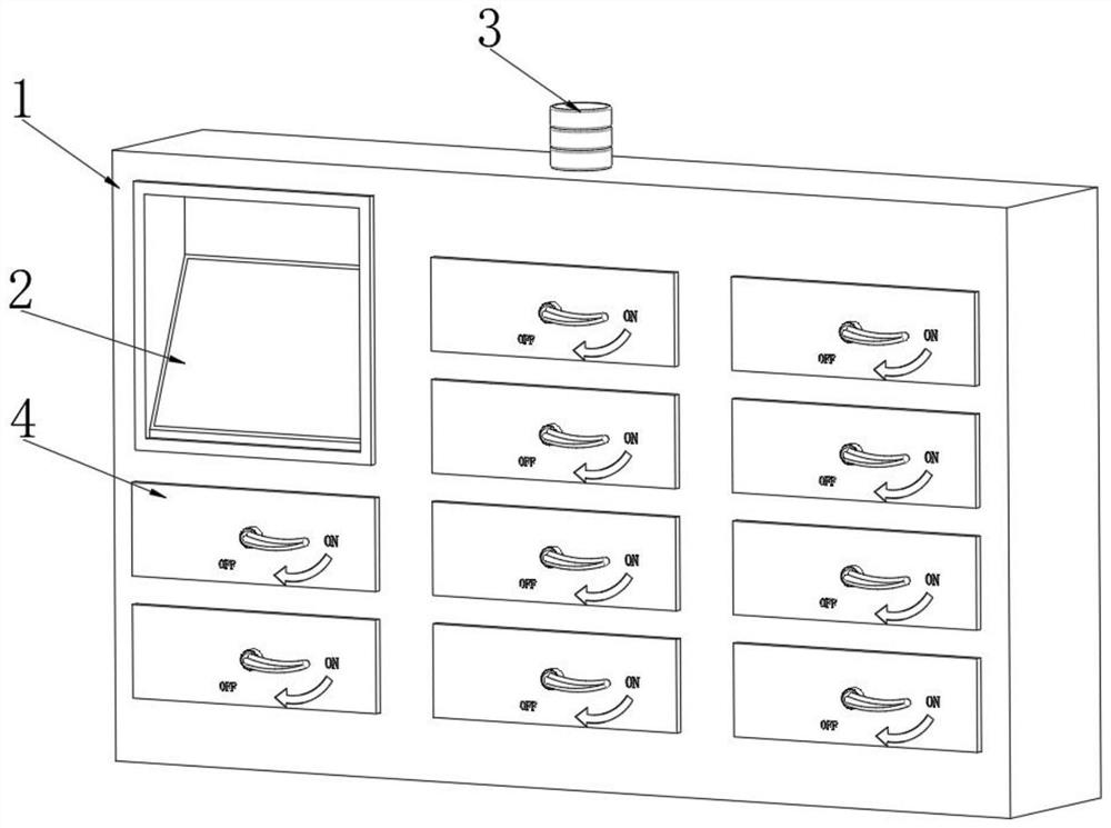
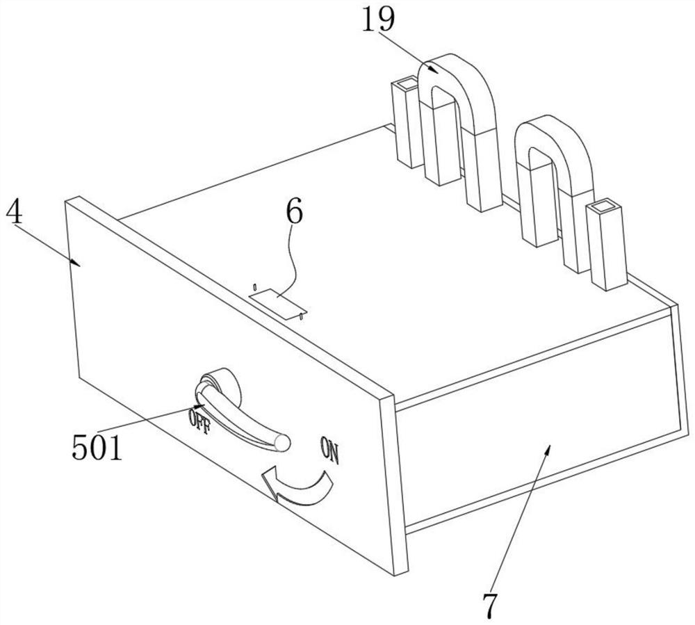
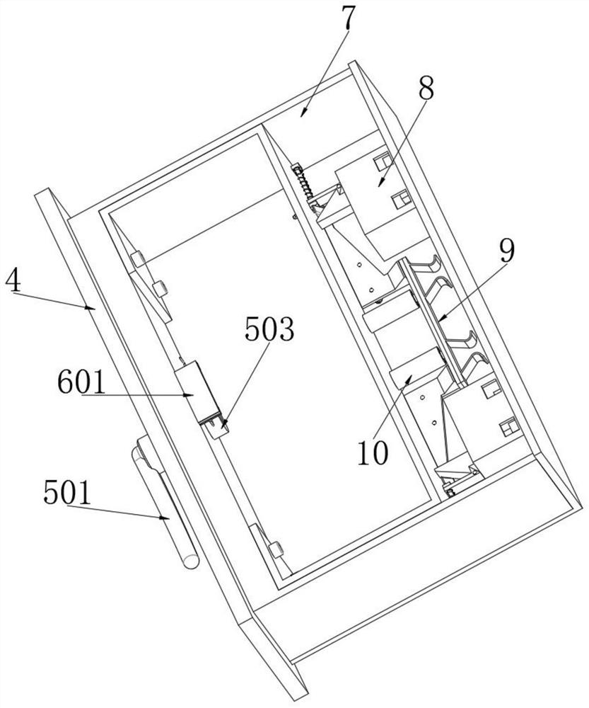
A low-voltage withdrawable switch cabinet
A low-voltage withdrawable switchgear technology, applied in the field of switchgear, can solve problems such as difficult self-extinguishing, arcing (relative to ground or phase-to-phase short circuit, endangering personal safety, etc.
- Summary
- Abstract
- Description
- Claims
- Application Information
AI Technical Summary
Problems solved by technology
Method used
Image

Examples
Embodiment Construction
[0027]The implementation of the present invention is described below through specific specific examples, and those skilled in the art can understand the advantages and effects of the present invention from the content disclosed in this specification. It should be noted that the diagrams provided in the following examples are for illustrative purposes only, and are only schematic diagrams rather than actual pictures, and should not be construed as limitations on the present invention. In order to better illustrate the embodiments of the present invention , some components in the figure will be omitted, enlarged or reduced, and do not represent the size of the actual product; for those skilled in the art, it is understandable that some known structures and their descriptions in the figure may be omitted.
[0028] The same or similar symbols in the figures of the embodiments of the present invention correspond to the same or similar components. In the description of the present in...
PUM
 Abstract
Description
Claims
Application Information