
Novel hinge component

A technology of hinges and components, which is applied to hinges, door/window accessories, hinges with pins, etc. It can solve the problems of inconvenient disassembly and installation, damage to door paint and wood panels, and increase installation costs, etc., to achieve easy processing , low cost and strong practicability

Inactive Publication Date: 2012-07-18
SUZHOU WUZHONG DONGFANG COMPLETE SET ELECTRICAL EQUIP
View PDF0 Cites 2 Cited by
  • Summary
  • Abstract
  • Description
  • Claims
  • Application Information

AI Technical Summary

Problems solved by technology

[0002] Hinges are usually used on objects that need to be rotated, such as doors and windows. The hinges in the prior art are composed of two blades and a connecting shaft. The two blades can rotate around the connecting shaft. The hinges cannot be disassembled
After the hinge is installed on the door and the door frame, if the door needs to be replaced, all the screws connecting the door and one of the leaves must be removed before disassembly, and generally multiple hinges are installed between the door and the door frame. It is very inconvenient to disassemble and install, and a lot of time is wasted
In order to ensure that the door or window can be kept open on the market, it is necessary to be equipped with a door catch assembly or a window support assembly, wherein the door catch assembly is composed of a concave block fixed on the bottom of the door and a wall fixed on the wall behind the door. Composed of bumps, it will inevitably damage the door and wall surface during installation, not only will it damage the paint and wood panels on the door, but it will also be unsightly when the door is closed
In addition, the added door catch assembly or window support assembly also increases the installation cost

Method used


Image

  • Novel hinge component
  • Novel hinge component
  • Novel hinge component

Examples


Embodiment Construction

[0015] The present invention is described below in conjunction with accompanying drawing.

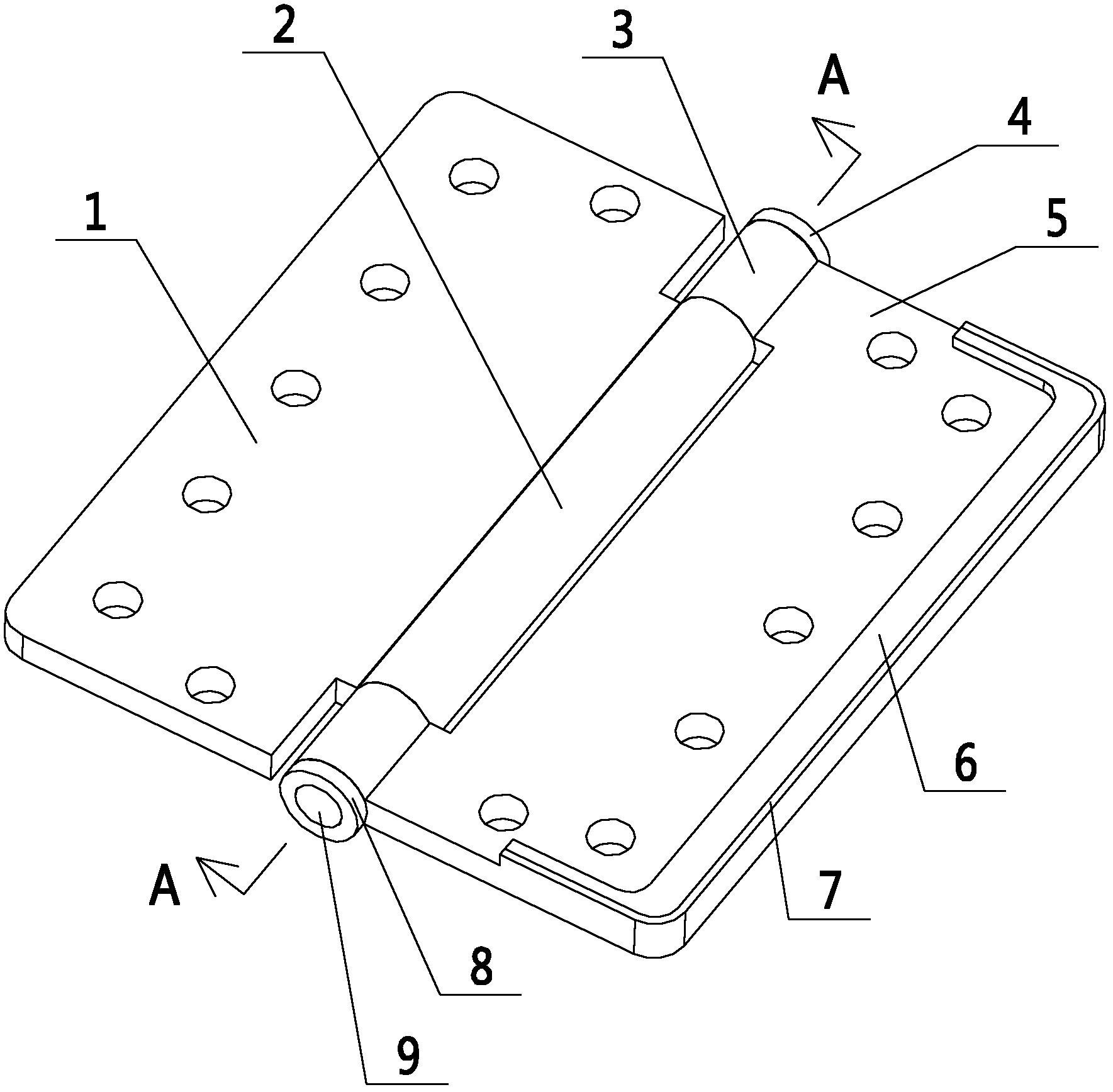
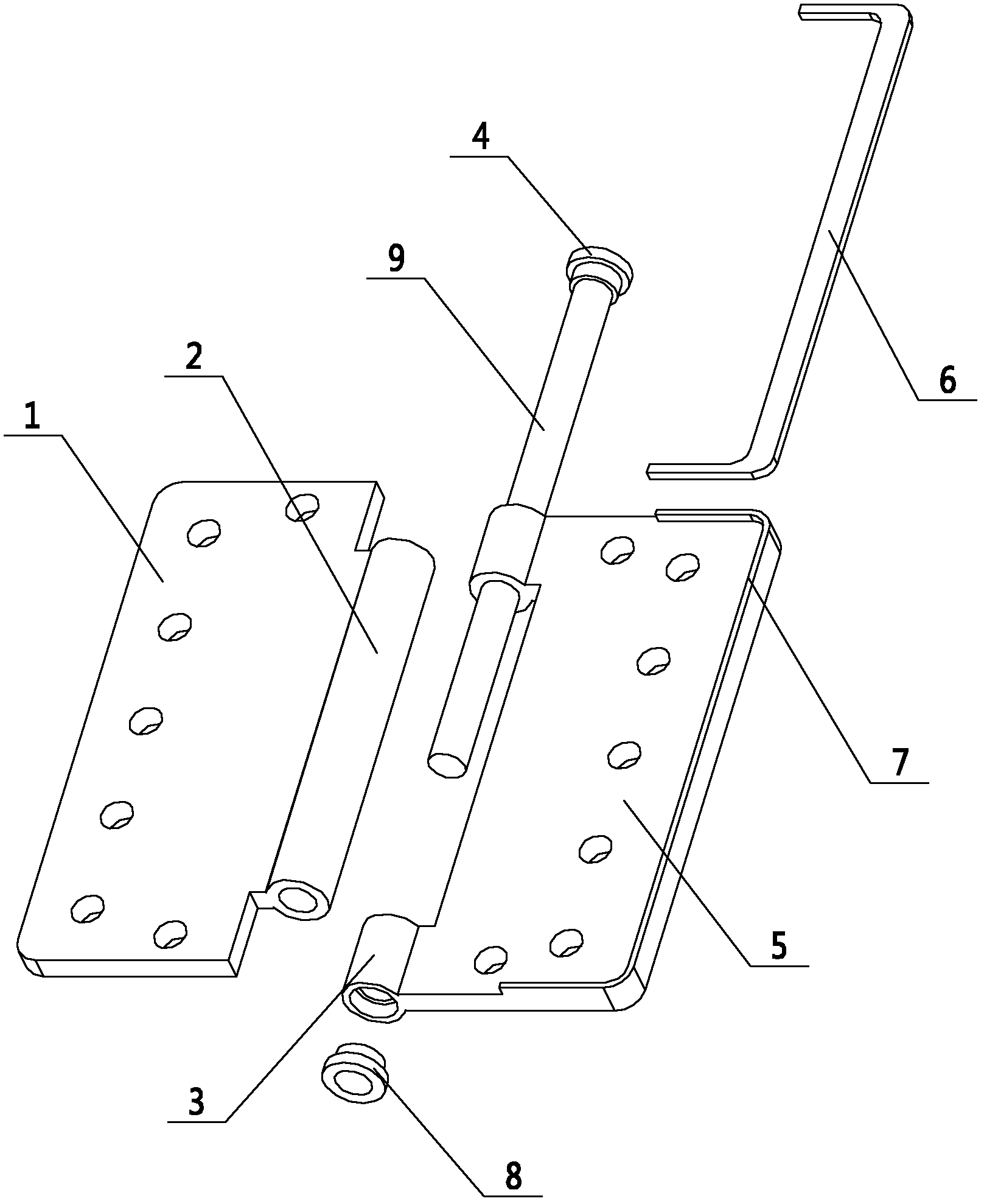
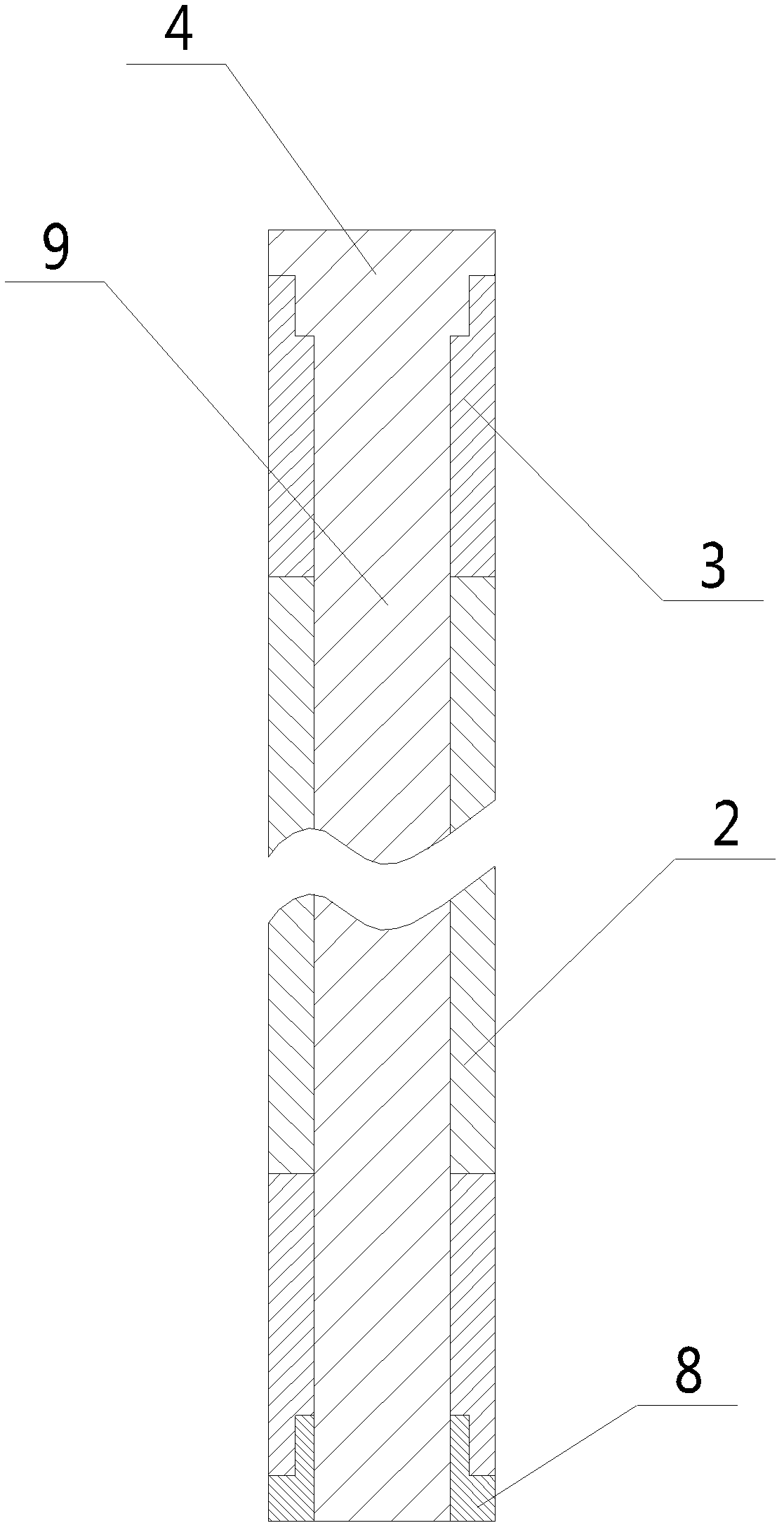
[0016] as attached figure 1 , 2 , 3 shows a new type of hinge assembly according to the present invention, including a shaft cover 8, a magnetic block 6, a first blade 1, a second blade 5, and a connecting shaft 9; One side of the two blades 5 is fixed with a first shaft sleeve 2; on the second blade 5, a second shaft sleeve 3 is fixed near the side of the first blade 1; the first shaft sleeve 2 and the second shaft sleeve 3. Arranged across each other; the connecting shaft 9 passes through the first bushing 2 and the second bushing 3, and rotatably connects the first blade 1 and the second blade 5 together; the connecting shaft 9 One end is extended with a boss 4, and the outer cover of the boss 4 is on the outer end surface of the second shaft sleeve 3; In the hole, the outer cover of the large-diameter end is on the end face of the second shaft sleeve 3; the other end of the conn...


PUM


Abstract

The invention discloses a novel hinge component. The novel hinge component comprises a shaft cover, a magnetic block, two blades and a connecting shaft, wherein shaft sleeves extend from the opposite sides of the two blades in a mutual intersecting manner; the connecting shaft penetrates through the shaft sleeves, and the two blades are rotatably connected together; a boss extends from one end of the connecting shaft, and covers on the outer end surfaces of the shaft sleeves; the other end of the connecting shaft is provided with a thread groove; the thread groove is provided with a shaft cover matched with the thread groove; a U-shaped blocking strip also extends from the edge of one blade; and the magnetic block is arranged in the blocking strip and is fixed on the blade. The novel hinge component disclosed by the invention has the advantages that a door or a window can be easily disassembled, and the replacement of the door and the window and the like is very convenient; the opened states of the door and the window and the like can be guaranteed, the structure is simple, the cost is low and the use is also very convenient; and the design is simple, the processing is easy, the requirement on large-batch production can be met, and the practicability is strong.

Description

technical field [0001] The invention relates to a hardware connector, in particular to a novel hinge assembly, which belongs to the technical field of hardware connectors. Background technique [0002] Hinges are usually used on objects that need to be rotated, such as doors and windows. The hinges in the prior art are composed of two blades and a connecting shaft. The two blades can rotate around the connecting shaft. The hinges cannot be disassembled. After the hinge is installed on the door and the door frame, if the door needs to be replaced, all the screws connecting the door and one of the leaves must be removed before disassembly, and generally multiple hinges are installed between the door and the door frame. It is very inconvenient during disassembly and installation, and a lot of time is wasted. In order to ensure that the door or window can be kept open on the market, it is necessary to be equipped with a door catch assembly or a window support assembly, wherein...

Claims


Application Information

Patent Timeline
Patent Type & Authority Applications(China)
IPC IPC(8): E05D7/10E05D3/02E05D5/04
Inventor 蔡玉明
Owner SUZHOU WUZHONG DONGFANG COMPLETE SET ELECTRICAL EQUIP
Learn More