Radiation patch array and planar microstrip array antenna

A radiating patch and array technology, applied in the direction of antenna, antenna array, radiating element structure, etc., can solve the problems of large loss, high antenna cost, narrow bandwidth, etc., to reduce antenna cost, improve array noise performance, reduce antenna The effect of size

Pending Publication Date: 2020-11-24
SUPER TELECOM CO LTD +1
View PDF18 Cites 2 Cited by
  • Summary
  • Abstract
  • Description
  • Claims
  • Application Information

AI Technical Summary

Problems solved by technology

[0006] The purpose of the present invention is to provide a radiation patch array and a planar microstrip array antenna, which can solve the problems of high cost, narrow bandwidth and large loss of microstrip array antennas in the prior art

Method used


Image

  • Radiation patch array and planar microstrip array antenna
  • Radiation patch array and planar microstrip array antenna
  • Radiation patch array and planar microstrip array antenna

Examples


Embodiment Construction

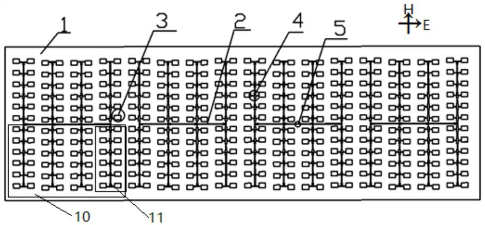
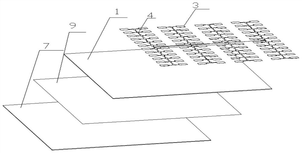
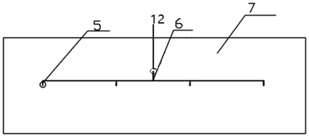
[0021] Embodiments of the present disclosure will be described in detail below in conjunction with the accompanying drawings.

[0022] Embodiments of the present disclosure are described below through specific examples, and those skilled in the art can easily understand other advantages and effects of the present disclosure from the contents disclosed in this specification. Apparently, the described embodiments are only some of the embodiments of the present disclosure, not all of them. The present disclosure can also be implemented or applied through different specific implementation modes, and various modifications or changes can be made to the details in this specification based on different viewpoints and applications without departing from the spirit of the present disclosure. It should be noted that, in the case of no conflict, the following embodiments and features in the embodiments can be combined with each other. Based on the embodiments in the present disclosure, a...


PUM


Abstract

The invention provides a radiation patch array and a planar microstrip array antenna. The radiation patch array is composed of n columns of radiation patch linear arrays. The radiation patch linear array is composed of m rows of radiation patch units. The radiation patch unit comprises a cross-shaped power division network and two rectangular patches. The cross-shaped power dividing network is ofa four-port structure, a left port and a right port are respectively connected with a rectangular patch, and the rectangular patches are excited in a parallel connection mode. And the upper ports andthe lower ports are respectively connected with the upper ports or the lower ports of the adjacent cross-shaped power division networks in the same column in series. The radiation patch linear array excites the rectangular patches in a parallel series feed mode, constructive radiation superposition is achieved in the wide edge direction of the rectangular patches, the length of a transmission lineis reduced by one time, meanwhile, the size of the antenna is reduced, and the cost of the antenna is effectively reduced. Meanwhile, because the feed loss is reduced, the noise performance of the array is improved, and the radiation efficiency and the gain bandwidth performance of the array are improved.

Description

technical field [0001] The invention relates to the technical field of microstrip antennas, in particular to a radiation patch array and a planar microstrip array antenna. Background technique [0002] In the field of modern mobile communication, the antenna is the core device of wireless microwave communication, and its envelope characteristics and integrability are more and more important to the communication quality. Compared with commonly used microwave antennas, microstrip antennas have the advantages of small size, light weight, simple fabrication, easy integration, and convenient conformality. Microstrip antennas can be widely used in airborne radar, satellite communication, mobile communication and satellite TV systems, significantly reducing the space occupied by communication equipment and improving the performance of communication equipment. [0003] Due to the low gain, wide beam and low radiation efficiency of the microstrip antenna unit, in order to achieve th...

Claims


Application Information

Patent Timeline
Patent Type & Authority Applications(China)
IPC IPC(8): H01Q1/38H01Q21/06
CPCH01Q1/38H01Q21/065
Inventor 尤阳陆云龙万军雷霄楚黄季甫符传波
Owner SUPER TELECOM CO LTD
Why Eureka
Try Eureka