
Induction lock locking mechanism

A lock mechanism and lock control technology, which is applied in the field of locks, can solve the problems of lack, inability to engage, and poor convenience of use, etc.

Active Publication Date: 2021-11-02
TOYO JIANN TSANG ELECTRIC CO LTD +1
View PDF0 Cites 0 Cited by
  • Summary
  • Abstract
  • Description
  • Claims
  • Application Information

AI Technical Summary

Problems solved by technology

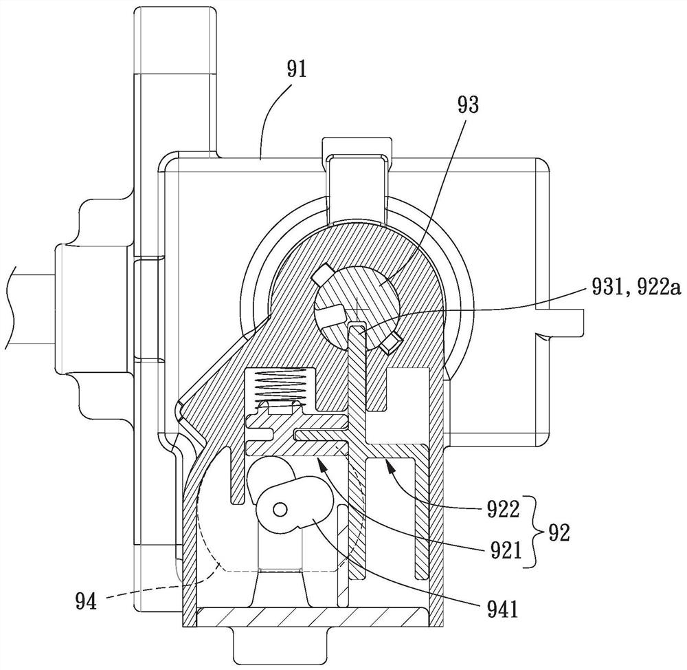
[0003] However, in the above-mentioned existing inductive lock 9, when the user intends to open a fuel tank or a seat cushion, if the sliding module 92 performs an automatic locking action, it often happens that the mandrel 93 does not rotate to the position, Make the locking portion 922a abut against the outer wall of the mandrel 93; at this time, even if the mandrel 93 continues to be rotated, one of the grooves 931 of the mandrel 93 is aligned with the locking portion 922a. The force of the displacement of the second slider 922 towards the direction of the spindle 93 makes the locking part 922a still unable to engage in one of the grooves 931, resulting in a situation where the lock cannot be secured, resulting in poor usability

Method used


Image

  • Induction lock locking mechanism
  • Induction lock locking mechanism
  • Induction lock locking mechanism

Examples


Embodiment Construction

[0069] In order to make the above and other objects, features and advantages of the present invention more comprehensible, the preferred embodiments of the present invention are listed below, together with the accompanying drawings, as follows:

[0070] Directionality or similar terms used throughout the invention, such as "front", "rear", "left", "right", "upper (top)", "lower (bottom)", "inner", "outer" , "side", etc., mainly refer to the directions of the drawings, and each direction or its approximate terms are only used to assist in explaining and understanding various embodiments of the present invention, and are not intended to limit the present invention.

[0071] The elements and components described throughout the present invention use the quantifier "a" or "an" only for convenience and to provide the usual meaning of the scope of the present invention; in the present invention, it should be interpreted as including one or at least one, and singular The notion of als...


PUM


Abstract

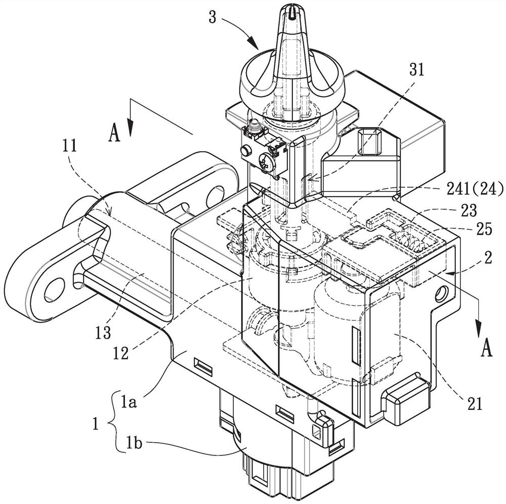
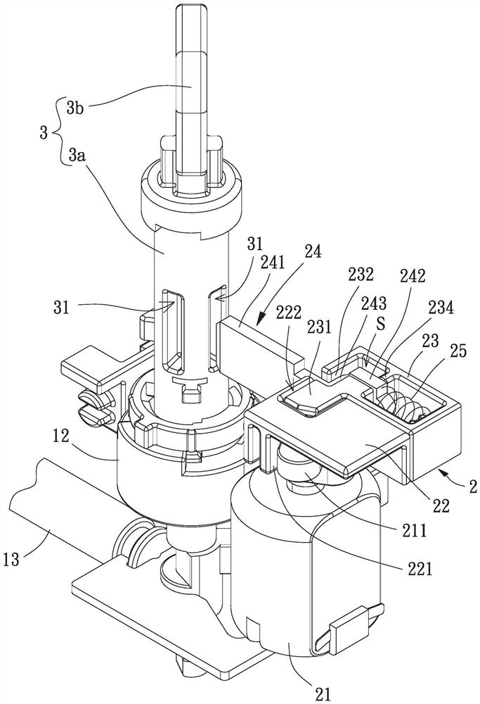
An inductive lock locking mechanism is used to solve the problem of poor convenience in use of existing inductive locks, which includes: a base with a housing and a linkage, the linkage is movably In the housing; a lock control module, which has a combined first slider and a second slider, and a locking part of a third slider passes through the first slider and the second slider Between, a support portion of the third slider is located in the second slider, an elastic element abuts against the second slider and the support portion, and the first slider is pushed by a power element to drive the first slider. Two sliders; and a switching element, which has a mandrel extending into the housing and combined with the linkage, the mandrel has a plurality of grooves, one of the grooves of the mandrel is used for the third slider The click part is clicked.

Description

technical field [0001] The invention relates to a lock, in particular to an induction lock locking mechanism for an electric vehicle. Background technique [0002] Electric vehicles have the advantages of light weight, no air pollution, and no noise. They are a means of transportation that can meet current environmental protection regulations. Please refer to figure 1 , which is an existing inductive lock 9 for electric vehicles, the existing inductive lock 9 has a housing 91 and a sliding module 92 located in the housing 91, the sliding module The set 92 has a combined first sliding block 921 and a second sliding block 922 , a mandrel 93 penetrates into the casing 91 , and the mandrel 93 has a plurality of grooves 931 . A block body 941 of a motor 94 can push the first slider 921, so that a locking portion 922a of the second slider 922 can be smoothly locked in one of the grooves 931 of the spindle 93, so that The locking function is achieved; at this time, the locking s...

Claims


Application Information

Patent Timeline
Patent Type & Authority Patents(China)
IPC IPC(8): B62H5/00
CPCB62H5/001B62H5/006
Inventor 潘申安胡至斌简永盛
Owner TOYO JIANN TSANG ELECTRIC CO LTD
Learn More