Multifunctional patrol inspection robot for railway signal machine room
A technology for inspecting robots and railway signals, which is applied to manipulators, program-controlled manipulators, manufacturing tools, etc., and can solve the problems of single motion trajectory and large shooting dead angle
- Summary
- Abstract
- Description
- Claims
- Application Information
AI Technical Summary
Problems solved by technology
Method used
Image
Examples
Embodiment 1
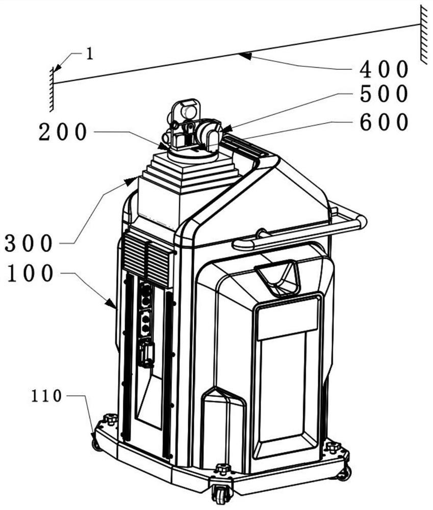
[0103] like figure 1 As shown, the multi-functional inspection robot in the railway signal room of the present application includes a robot main body 100, a sub-robot 200, a sub-robot lifting device 300, guide rails, a communication module, a control unit, a power supply system and a detection module.
[0104] The robot main body 100 supports and positions the various parts of the inspection robot, on which a robot walking device 110, a sub-robot lifting device 300 and a detection module are positioned; the robot walking device 110 plays a role in driving the robot main body 100 The function of walking and steering is positioned at the bottom of the robot main body 100, and the structure can be wheels and / or crawlers; the sub-robot lifting device 300 is fixedly connected in the robot main body 100 to play the role of lifting the sub-robot. The role of the robot 200, the structure of the sub-robot lifting device 300 can be a telescopic rod, which is a prior art, and will not be...
Embodiment 2
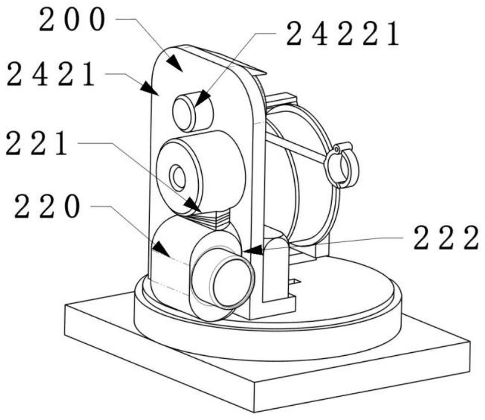
[0117] In order to further improve the shooting effect of the visible light pan-tilt camera 220 and shorten the shooting distance, this embodiment adds a camera lowering device 221 to the sub-robot 200 on the basis of the first embodiment, as image 3 or Figure 9As shown, the camera lowering device 221 is fixedly connected to the sub-robot main body 210, so as to lower the visible light pan-tilt camera 220 from the sub-robot main body 210 and make it close to the equipment to be inspected The effect of the camera lowering device 221 can be a combination of a hoist and a visible light pan-tilt camera positioning device; the hoist is positioned on the sub-robot main body 210, and the hoist includes a hoist main body and a hoist rope, and the hoist One end of the lifting rope is fixedly connected to the visible light pan-tilt camera 220; the visible light pan-tilt camera 220 is detachably positioned on the sub-robot main body 210; the visible light pan-tilt camera positioning de...
Embodiment 3
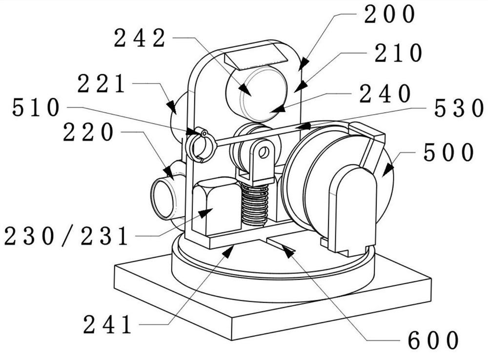
[0122] Considering that simply adopting the sub-robot guide rail 400 pre-arranged in the railway signal room will still greatly limit the running track of the sub-robot 200, there are more dead ends for inspection; figure 2 and Figure 10 As shown, this embodiment adds a temporary guide rail laying device and a sub-robot rope up and down device 600 on the basis of the above-mentioned embodiments, and uses the inspection robot to erect a new guide rail with the aid of the sub-robot guide rail 400 to improve the above problems.
[0123] The guide rail also includes a temporary guide rail laying device; the temporary guide rail laying device includes a retractable rope row 500, and the retractable rope row 500 is positioned on the top of the sub-robot lifting device 300, including a rope end positioning device 510, guide rail rope 520 and guide rail rope positioning tube 530; the guide rail rope 520 is wound on the described retractable rope row 500, one end of the guide rail ro...
PUM
 Abstract
Description
Claims
Application Information
 - R&D
- Intellectual Property
- Life Sciences
- Materials
- Tech Scout
- Unparalleled Data Quality
- Higher Quality Content
- 60% Fewer Hallucinations
Browse by: Latest US Patents, China's latest patents, Technical Efficacy Thesaurus, Application Domain, Technology Topic, Popular Technical Reports.
© 2025 PatSnap. All rights reserved.Legal|Privacy policy|Modern Slavery Act Transparency Statement|Sitemap|About US| Contact US: help@patsnap.com


