Eureka AIR delivers breakthrough ideas for toughest innovation challenges, trusted by R&D personnel around the world.

Temperature compensation method and system for display brightness

A temperature compensation and display technology, applied in static indicators, instruments, etc., can solve the problems of display defects and inability to meet the temperature compensation scheme, and achieve the effect of stable luminous brightness

Active Publication Date: 2020-12-25
ANHUI SEMICON INTEGRATED DISPLAY TECH CO LTD
View PDF16 Cites 2 Cited by
  • Summary
  • Abstract
  • Description
  • Claims
  • Application Information

AI Technical Summary

Problems solved by technology

However, for complex brightness modes, existing temperature compensation schemes cannot satisfy and will bring display defects

Method used


Image

  • Temperature compensation method and system for display brightness
  • Temperature compensation method and system for display brightness
  • Temperature compensation method and system for display brightness

Examples


Embodiment 1

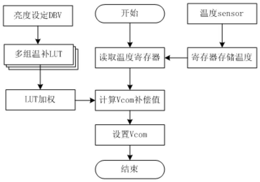
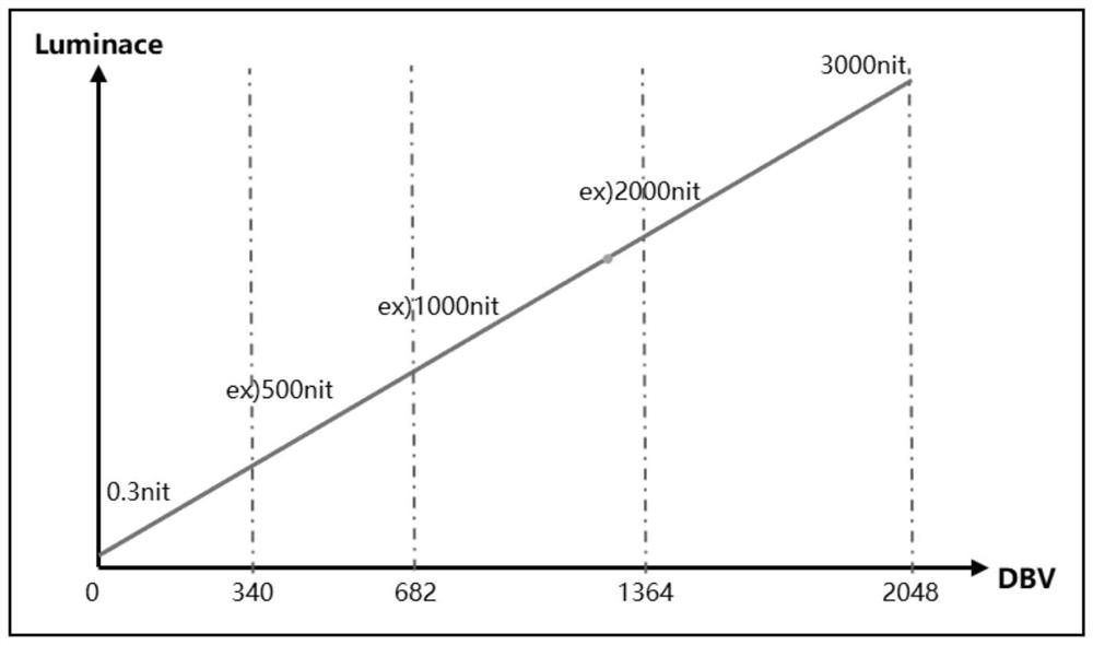
[0034] The compensation table has basic compensation values ​​for different ambient temperature divisions, and weighting factors for different brightness modes. The voltage compensation value is obtained by multiplying the basic compensation value of the current environment by the weighting factor of the current brightness mode, as shown in Table 2. Add the DBV weighting factor to the existing LUT, which changes with the change of DBV, so as to perform differential temperature compensation for different brightness modes. This factor needs to be obtained after testing data;

[0035] Current Temperature Vcom compensation value -40℃ δ DBV ×ΔV1

[0036] Table 2

Embodiment 2

[0038] The compensation table is provided with voltage compensation value groups for different ambient temperature divisions, and the voltage compensation value groups are composed of voltage compensation values ​​for different brightness modes at the ambient temperature, as shown in Table 3;

[0039] Current Temperature DBV1 DBV2 DBV3 …… -40℃ ΔV1 ΔV1′ ΔV1″ …… -38℃ ΔV2 ΔV2′ ΔV2″ …… -36℃ ΔV3 ΔV3′ ΔV3″ …… -34℃ ΔV4 ΔV4′ ΔV4″ …… …… …… …… …… …… 50℃ ΔVn-3 ΔVn-3′ ΔVn-3″ …… 60℃ ΔVn-2 ΔVn-2′ ΔVn-2″ …… 70℃ ΔVn-1 ΔVn-1′ ΔVn-1″ …… 80℃ ΔVn Δvn' Δvn″ ……

[0040] table 3

[0041] If the current ambient temperature is between the two ambient temperature points in the compensation table, then obtain the compensation values ​​of the two ambient temperature points according to the current brightness mode, and use linear interpolation or other interpolation methods to obtain them. F...


PUM


Abstract

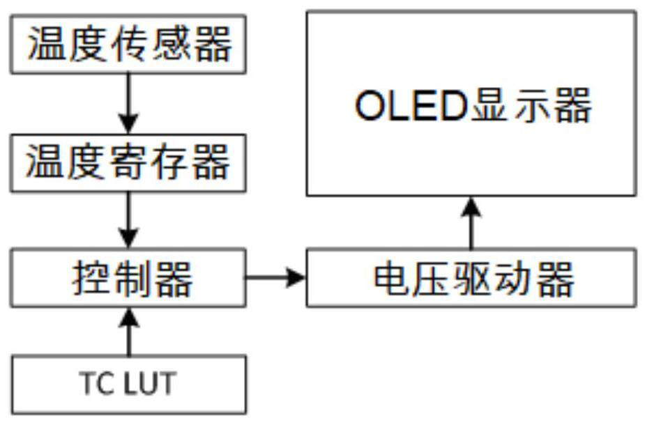
The invention discloses a temperature compensation method for display brightness. The temperature compensation method comprises the following steps of 1) acquiring an ambient temperature, 2) obtaininga current brightness mode, 3) looking up a table according to the current brightness mode and the ambient temperature to obtain a voltage compensation value, and 4) transmitting the voltage compensation value to a voltage driver. A plurality of groups of temperature compensation LUTs are added in the temperature compensation system of the OLED display system, and a group of compensation methods are disclosed to carry out temperature compensation on the OLED display system under different temperatures and different brightness modes, so that the problem that the luminous brightness of the OLEDdisplay system is changed along with the temperature is solved, and the luminous brightness of the display system under various scenes is stabilized.

Description

technical field [0001] The invention relates to the field of electronic products, in particular to the design of temperature compensation technology for OLED displays. Background technique [0002] With the development of display technology, AMOLED display technology has gradually matured. Compared with LCD display, it has obvious advantages such as high brightness, full color, high contrast, lower driving voltage and faster response time. AMOLED displays are also gradually pouring into the market, which is bound to replace traditional LCD displays. As a next-generation display technology, AMOLED display has a good development prospect. However, AMOLED display technology still has obvious defects. Since the luminance of OLED devices will change with temperature, when the ambient temperature changes, it is necessary to change the driving conditions of the OLED panel to compensate the luminance to offset the brightness drift caused by temperature changes, so that the displa...

Claims


Application Information

Patent Timeline
Patent Type & Authority Applications(China)
IPC IPC(8): G09G3/3208G09G3/3258
CPCG09G3/3208G09G3/3258G09G2320/0626
Inventor 颜伟男刘胜芳赵铮涛王志超
Owner ANHUI SEMICON INTEGRATED DISPLAY TECH CO LTD
Why Eureka
Eureka Blog
Learn More