Dielectric filter and dielectric duplexer

A dielectric filter and duplexer technology, applied in waveguide devices, resonators, electrical components, etc., can solve problems such as differences in the characteristics of electrodes or electrical probes of dielectric filters, and achieve the effect of increasing dielectric strength

Inactive Publication Date: 2003-09-17
MURATA MFG CO LTD
View PDF1 Cites 0 Cited by
  • Summary
  • Abstract
  • Description
  • Claims
  • Application Information

AI Technical Summary

Problems solved by technology

This discharge can cause differences in the characteristics of the dielectric filter's electrodes or electrical probes

Method used


Image

  • Dielectric filter and dielectric duplexer
  • Dielectric filter and dielectric duplexer
  • Dielectric filter and dielectric duplexer

Examples


Embodiment Construction

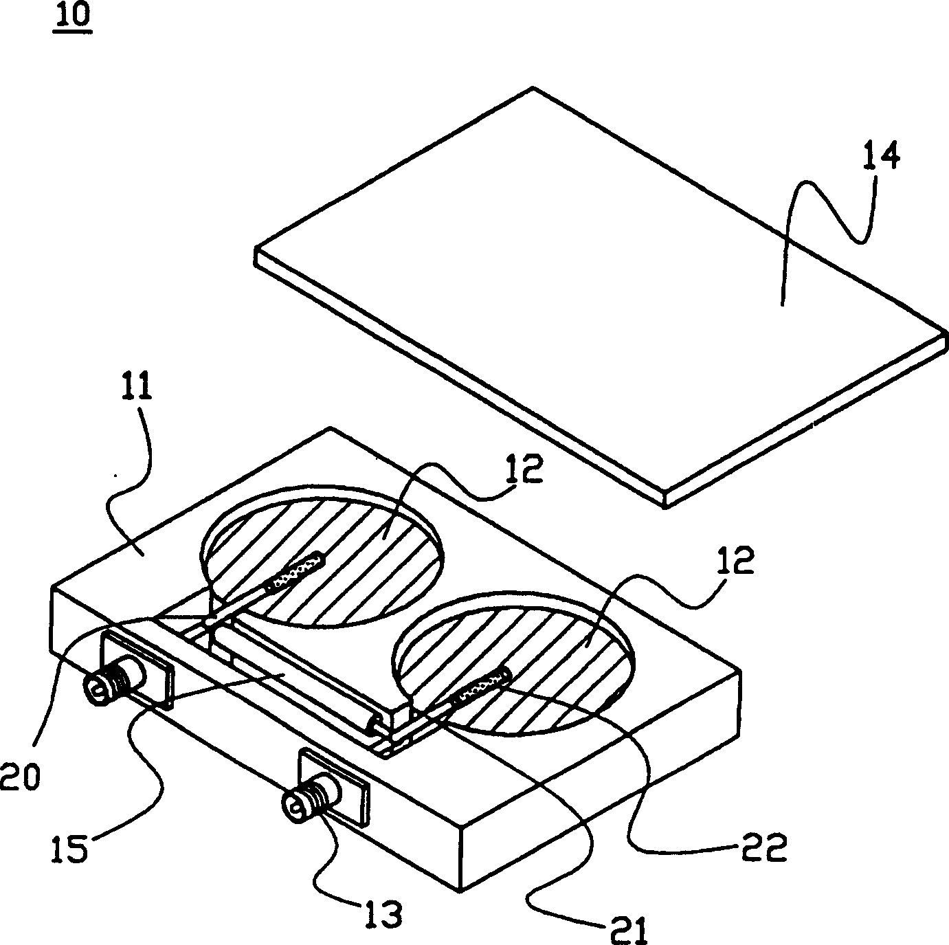
[0025] now refer to figure 1 , an embodiment of the dielectric filter according to the present invention will be described below. figure 1 is the perspective of the dielectric filter 10 according to the present invention picture . in the picture In , the upper cover 14 is removed so that the internal structure can be seen.

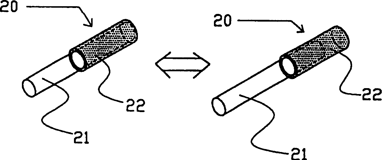
[0026] The dielectric filter 10 includes a shielded cavity frame 11 , a disk-shaped dielectric 12 and an external coupling device 20 . The shield cavity frame 11 is formed of metal, and external connectors 13 are attached thereto so that signals are output to or input from the outside through cables. The external coupling means 20 are connected to the respective external terminals 13 by solder. Each dielectric 12 is formed of ceramics in a disk shape, and electrodes are formed on the dielectric by applying and baking silver paste on both relevant surfaces. The lower surface of each dielectric 12 is fixed to the inner bottom surface of the shield ...


PUM


Abstract

The dielectric filter includes a conductive shielding cavity frame; its two relevant surfaces have electrodes and are arranged on a dielectric in the shielding cavity frame; and external coupling means, wherein the external coupling means includes electrical probes, At least a portion of the electrical probe is covered by a covering dielectric.

Description

technical field [0001] The present invention relates to a dielectric filter and a dielectric duplexer used in communication base stations and the like. Background technique [0002] Figure 7 A dielectric filter related to the present invention is shown. Although such a dielectric filter is disclosed in pending U.S. Patent Application No. 924040, when this invention was filed as Japanese Patent Application No. H-10-8860 (the present application claims priority based on this invention), Such dielectric filters are not known in the prior art. [0003] Figure 7 is the perspective of the dielectric filter 110 picture . in the picture In , the upper cover 114 is removed so that the internal structure can be seen. The dielectric filter shown here is of the type as a two-stage band rejection filter, and includes two disc-shaped dielectrics 112 arranged side by side in a shielded cavity frame 111 . [0004] The dielectric filter 110 includes a shielded cavity frame 111, whi...

Claims


Application Information

Patent Timeline
Patent Type & Authority Patents(China)
IPC IPC(8): H01P1/20H01P1/208H01P1/213H01P5/04H01P7/10
CPCH01P1/2084H01P5/04H03H9/30
Inventor 久保田和彦伊势智之
Owner MURATA MFG CO LTD
Why Eureka
Try Eureka