Self-moving and landing guidance method and system for rotor UAV

An autonomous mobile, unmanned rotor technology, applied in the control/adjustment system, non-electric variable control, three-dimensional position/channel control, etc., can solve problems such as time rush, drone rollover damage, roughness, etc., to improve landing speed and the effect of reducing the risk of rollover

Active Publication Date: 2021-10-12
BEIJING INSTITUTE OF TECHNOLOGYGY
View PDF14 Cites 0 Cited by
  • Summary
  • Abstract
  • Description
  • Claims
  • Application Information

AI Technical Summary

Problems solved by technology

As a result, there is currently no algorithm that can well meet the needs of autonomous mobile landing, and the technology of autonomous landing of mobile targets cannot be popularized and applied in engineering
[0004] Most of the current autonomous landing technologies for moving targets use PID to cooperate with visual information to land in engineering. However, the robustness of PID control is poor, and it is greatly affected by the environment, resulting in low control accuracy. Large shakes will cause the drone to roll over and cause damage
Moreover, the landing time of this algorithm is relatively slow, and within the limited battery power, the time for the UAV to perform other tasks is relatively hasty, which will lead to low task efficiency
And when the visual information is about to land, as the altitude decreases, the UAV and the mobile platform gradually approach, and the selection of feature points for visual recognition is more difficult and rough, making it more difficult to obtain the target, making the landing accuracy lower. Easy to damage drones and platforms

Method used


Image

  • Self-moving and landing guidance method and system for rotor UAV
  • Self-moving and landing guidance method and system for rotor UAV
  • Self-moving and landing guidance method and system for rotor UAV

Examples


Embodiment

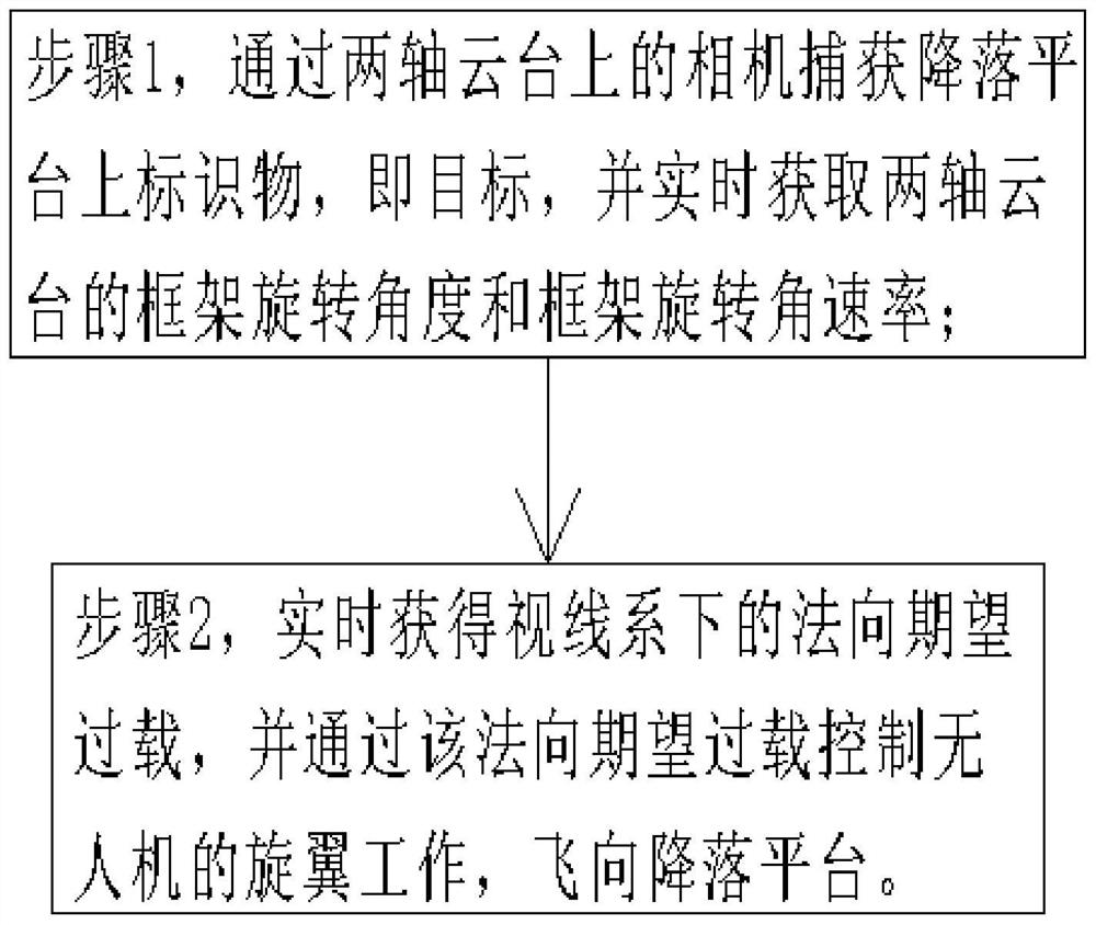
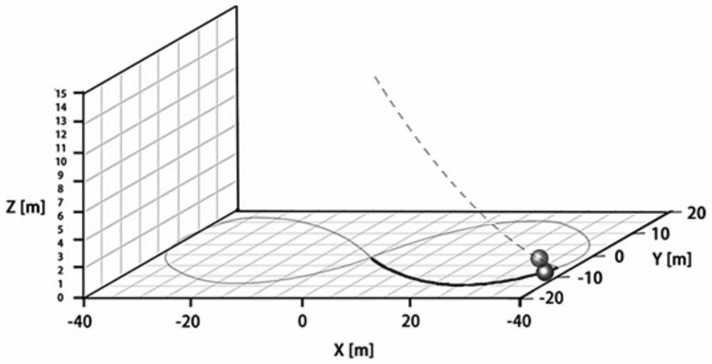
[0082] Taking the car cruising around the figure-eight route on the ground as the target, there is a marker on the top of the car that can be captured by the camera on the UAV; the target's trajectory is as follows: figure 2 shown by the solid line in

[0083] The initial position coordinates of the UAV are (0,0,15), when the UAV is at the initial position, the coordinates of the target location are (20,-14,0), and the initial speed of the UAV is 0m / s, the two-axis gimbal on the UAV can track the marker in real time, so that the marker is always in the center of the field of view, and output the frame rotation angle and frame rotation angular rate of the two-axis gimbal;

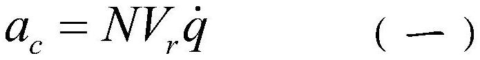
[0084] The UAV is guided and controlled by the autonomous movement and landing guidance method of the rotor UAV, and the normal expected overload is calculated in real time, and the UAV is controlled to fly to the target through the normal expected overload.

[0085] Specifically, the expected overload in...


PUM


Abstract

The invention discloses a method and system for guiding the autonomous movement and landing of a rotor UAV. The method enables the UAV to quickly, accurately and safely land on a mobile platform, improves the landing accuracy and speed, and ensures the safe recovery of the UAV. rate while leaving enough time for the UAV to perform other tasks. Specifically, the camera on the two-axis gimbal is used to capture the markers on the landing platform, and the angle and angular rate values ​​are obtained in real time; the guidance strategy adopts the PN algorithm that includes the speed and position constraints of the terminal to ensure that the UAV can land quickly and The terminal can implement speed constraints and position constraints, and the terminal makes the acceleration tend to 0. Such a guidance method makes the acceleration change of the unmanned aerial vehicle in the direction of the projectile line and the direction perpendicular to the projectile line in the LOS coordinate system small, and at the same time it can meet the conditions for the use of the proportional guidance algorithm, so that the rotor UAV can operate in the LOS coordinate system. Landing on the mobile platform is relatively stable, ensuring the safety of the UAV and achieving the goal of autonomous landing.

Description

technical field [0001] The invention relates to a control method and system for a rotor UAV, in particular to a method and system for autonomously moving and landing a rotor UAV. Background technique [0002] Due to the advantages of better maneuverability and low cost, rotor UAVs have been widely used. Rotor UAVs are widely used in scenarios such as post-disaster search and rescue and intelligence collection. Through the on-board camera and gimbal of the rotor UAV, the tracking and identification of moving targets can be realized, and the rapid landing on the mobile platform can accelerate the development of the rotor UAV, broaden the application scenarios, and enhance the application value. [0003] Since the rapid landing of the UAV on the mobile platform involves multi-disciplinary knowledge such as control, trajectory estimation, computer vision, etc., there are many problems, such as low positioning accuracy, slow processing speed, large tracking error, low landing acc...

Claims


Application Information

Patent Timeline
Patent Type & Authority Patents(China)
IPC IPC(8): G05D1/10
CPCG05D1/101
Inventor 王辉李帆林德福程子恒宋韬郑多范世鹏
Owner BEIJING INSTITUTE OF TECHNOLOGYGY
Why Eureka
Try Eureka