Permanent magnet-electromagnetic cooperative coupling high-speed electromagnetic valve with high dynamic response and low rebound

A high-speed solenoid valve and low rebound technology, which is applied in combustion engines, engine components, machines/engines, etc., can solve the problems that the solenoid valve cannot be opened and closed, hinders the rapid increase of the electromagnetic force of the solenoid valve, and the large Joule heat of the excitation coil. , to achieve the effects of improving the dynamic response, accelerating the seat of the armature, and accelerating the falling speed

Active Publication Date: 2022-05-31
HARBIN ENG UNIV
View PDF9 Cites 0 Cited by
  • Summary
  • Abstract
  • Description
  • Claims
  • Application Information

AI Technical Summary

Problems solved by technology

Instantaneous loading of high current can realize faster opening of the high-speed solenoid valve. However, for the electronically controlled fuel system of high-frequency pulse injection, excessive driving current will cause the excitation coil to generate large Joule heat. The high driving current causes the iron core to generate a large eddy current loss, which will hinder the rapid increase of the electromagnetic force of the solenoid valve and delay the rapid opening of the solenoid valve
In addition, faster opening and closing will cause a strong impact between the armature and the solenoid valve limit part / seat during the rising / falling process, resulting in multiple irregular rebounds after the armature reaches the limit, which cannot be achieved by high-speed solenoid valves One-shot full opening and closing

Method used


Image

  • Permanent magnet-electromagnetic cooperative coupling high-speed electromagnetic valve with high dynamic response and low rebound
  • Permanent magnet-electromagnetic cooperative coupling high-speed electromagnetic valve with high dynamic response and low rebound
  • Permanent magnet-electromagnetic cooperative coupling high-speed electromagnetic valve with high dynamic response and low rebound

Examples


Embodiment Construction

[0026] The present invention will be described in more detail below in conjunction with the accompanying drawings:

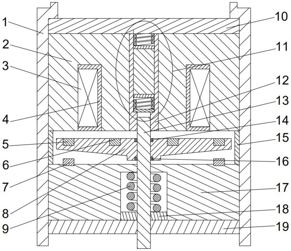
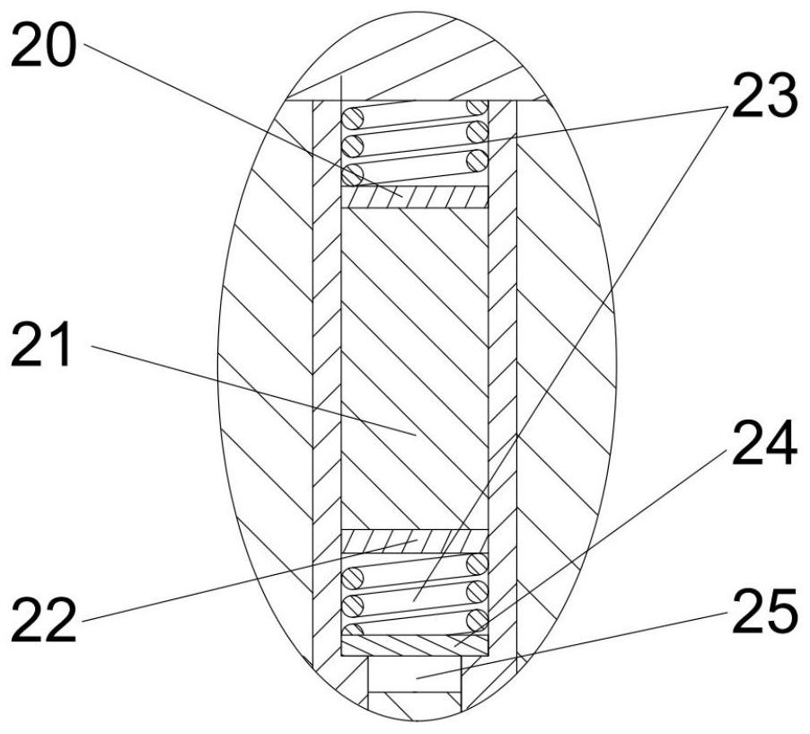
[0027] combine Figure 1-6 , the composition of the present invention includes shell 1, iron core 2, coil 3, coil bobbin 4, outer permanent magnet ring 5, inner permanent magnet ring 6, buffer permanent magnet ring 7, armature 8, armature return spring 9, fixing nut 10 , giant magnetostrictive assembly 11, spring limit sleeve 12, valve stem 13, armature upper snap ring 14, armature lift adjustment ring 15, armature lower snap ring 16, return spring cavity 17, return spring washer 18, tightening Secure the nut 19. The top and bottom of the casing 1 are respectively provided with a fixing nut 10 and a tightening nut 19, and an annular groove is formed on the iron core 2 to form the main magnetic pole and the auxiliary magnetic pole of the iron core. The coil 3 is wound in the bobbin 4, the radial width of the bobbin 4 is equal to the width of the annular groove ...


PUM


Abstract

The invention aims to provide a high-dynamic-response low-rebound permanent magnet-electromagnetism synergistic coupling high-speed electromagnetic valve which comprises a shell and an iron core, the iron core is installed in the shell, an axial center through hole is formed in the middle of the iron core, a spring limiting sleeve is installed in the axial center through hole, an armature and a reset spring cavity are sequentially arranged below the iron core, and a spring is installed in the reset spring cavity. The upper portion of the valve rod is located in a spring limiting sleeve, an upper disc permanent magnet, a lower disc permanent magnet and a spring gasket are arranged in the spring limiting sleeve, and a giant magnetostrictive body is installed between the upper disc permanent magnet and the lower disc permanent magnet. By means of the structure, the electromagnetic force generated when the armature is attracted can be effectively increased, the dynamic response speed is increased, rapid demagnetization of the iron core is facilitated, and the release speed of the armature is increased; and meanwhile, the bounce degree of the armature during attraction and seating can be reduced, and the working stability of the high-speed electromagnetic valve is improved on the basis that the dynamic performance of the high-speed electromagnetic valve is improved.

Description

technical field [0001] The invention relates to a diesel engine, in particular to a diesel engine high-pressure common rail device. Background technique [0002] The high-pressure common rail fuel injection system has the advantages of flexible and adjustable fuel injection law, fuel injection quantity and fuel injection timing, and can achieve the best fuel injection characteristics adjustment according to the specific working conditions of the engine. Therefore, modern diesel engines can achieve high efficiency and low emission. one of the core systems. The high-speed solenoid valve, as the core component of the high-pressure common rail system - the executive component of the common rail injector, undertakes the bridge between the electrical signal and the fuel injection characteristics. . [0003] In order to achieve precise control of fuel injection rules and more flexible multiple injections, the electronically controlled fuel system puts forward very high technical ...

Claims


Application Information

Patent Timeline
Patent Type & Authority Applications(China)
IPC IPC(8): F02M61/10F02M61/16F02M63/00
CPCF02M61/10F02M61/16F02M63/0017Y02T10/40F02M51/0635F02M51/0621H01F7/1646H01F7/081H01F7/088H01F7/122H01F7/1615
Inventor 赵建辉卢相东张恒徐煜刘伟龙
Owner HARBIN ENG UNIV
Why Eureka
Try Eureka