High-response high-speed electromagnetic valve with multiple permanent magnet-electromagnetic coupling magnetic circuits

A high-speed solenoid valve and electromagnetic coupling technology, which is applied in the direction of charging system, fuel injection device, combustion engine, etc., can solve the problems of large eddy current loss of the iron core, reduce the service life of the solenoid valve, and large Joule heat of the excitation coil, etc. Dynamic response, the effect of accelerating the falling speed

Active Publication Date: 2022-05-10
HARBIN ENG UNIV
View PDF11 Cites 0 Cited by
  • Summary
  • Abstract
  • Description
  • Claims
  • Application Information

AI Technical Summary

Problems solved by technology

Instantaneous loading of high current can realize faster opening of the high-speed solenoid valve. However, for the electronically controlled fuel system with high-frequency pulse injection, excessive driving current will cause the excitation coil to generate large Joule heat, which will affect the enameled wire material and The temperature-dependent characteristics of the iron core place higher demands and seriously reduce the service life of the solenoid valve
Moreover, the instantaneous loading of a large driving current causes a large eddy current loss in the iron core, which will hinder the rapid increase of the electromagnetic force of the solenoid valve and delay the rapid opening of the solenoid valve.

Method used


Image

  • High-response high-speed electromagnetic valve with multiple permanent magnet-electromagnetic coupling magnetic circuits
  • High-response high-speed electromagnetic valve with multiple permanent magnet-electromagnetic coupling magnetic circuits
  • High-response high-speed electromagnetic valve with multiple permanent magnet-electromagnetic coupling magnetic circuits

Examples


Embodiment Construction

[0021] The present invention is described in more detail below in conjunction with accompanying drawing example:

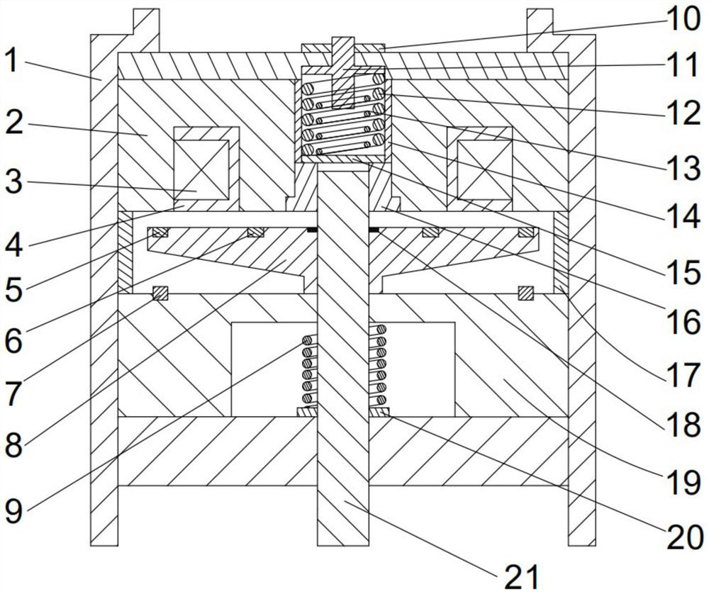
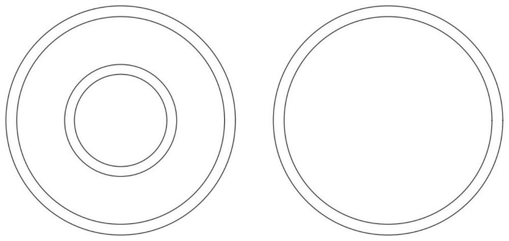
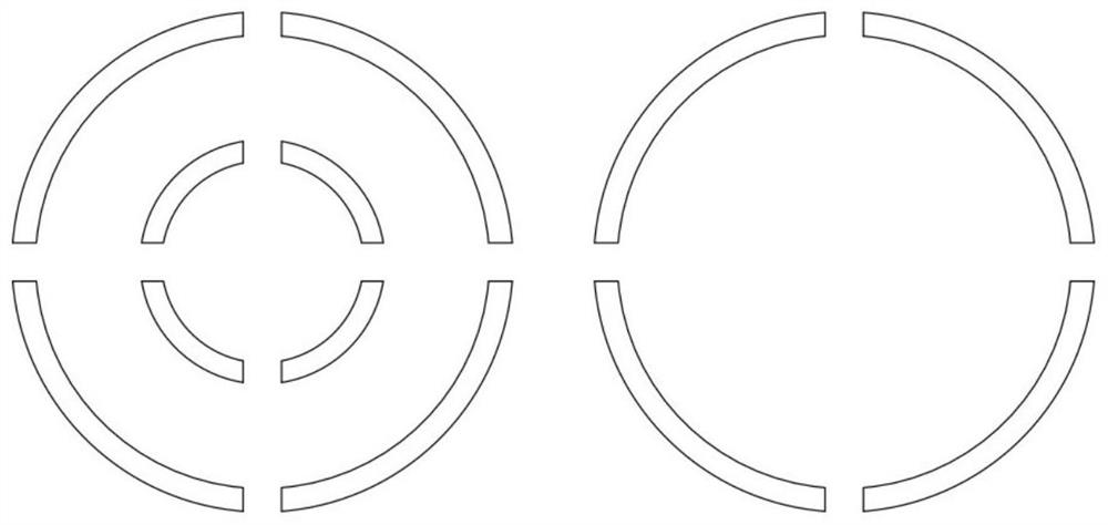
[0022] combine Figure 1-3 The composition of the present invention includes a housing 1, an iron core 2, a coil 3, a coil bobbin 4, an outer permanent magnet ring 5, an inner permanent magnet ring 6, a buffer permanent magnet ring 7, an armature 8, an armature return spring 9, and an adjustment nut 10 , Cross bolt 11, large buffer spring 12, small buffer spring 13, spring guide sleeve 14, spring washer 15, spring limit ring 16, armature lift adjustment ring 17, armature snap ring 18, return spring cavity 19, Return spring washer 20, valve stem 21. An annular groove is formed on the iron core 2 to form the main magnetic pole 23 and the auxiliary magnetic pole 25 of the iron core. The coil 3 is wound in the bobbin 4. The radial width of the bobbin 4 is equal to the width of the annular groove of the iron core, and the axial height is equal to or Less than the dep...


PUM


Abstract

The invention aims to provide a high-response high-speed electromagnetic valve with multiple permanent magnet-electromagnetic coupling magnetic circuits, which comprises a shell and an iron core, the iron core is mounted in the shell, an annular groove is formed in the iron core, a coil framework is embedded in the annular groove, a coil is wound on the coil framework, an axial central through hole is formed in the middle of the iron core, and the permanent magnet-electromagnetic coupling magnetic circuits are arranged in the axial central through hole. A spring guide sleeve and a spring limiting ring are installed in the axial center through hole, an armature and a reset spring cavity are sequentially arranged below the iron core, a valve rod penetrates through the reset spring cavity and the armature, the upper portion of the valve rod is located in the spring limiting ring, and the portion, located in the reset spring cavity, of the valve rod is sleeved with an armature reset spring. A cross-shaped bolt is installed above the spring guide sleeve through an adjusting nut, and a large buffering spring and a small buffering spring are installed in the spring guide sleeve. The dynamic response speed is increased, meanwhile, the buffer permanent magnet ring and the flexible buffer assembly can reduce the collision degree when the armature is attracted and seated, and the oil injection stability of the common rail oil injector is improved.

Description

technical field [0001] The invention relates to a diesel engine, in particular to a high-pressure common rail device for a diesel engine. Background technique [0002] The high-speed solenoid valve is the core component of the high-pressure common rail injector. It is the key for the common rail system to realize the flexible adjustment of the circulating fuel injection volume, fuel injection law and fuel injection timing. Its dynamic response characteristics are the main factors for evaluating the performance of the high-speed solenoid valve. index. In the work of the electronically controlled fuel system, the electronic control system loads the high-speed solenoid valve with a "peak-hold" current drive strategy, that is, in the armature lift phase, a larger drive voltage is used to generate a large drive current in an instant to achieve the armature lift speed. Speed ​​up, after the armature reaches the limit, adjust the pulse width of the 24V drive voltage to obtain a sm...

Claims


Application Information

Patent Timeline
IPC IPC(8): F02M63/00F02M63/02
CPCF02M63/0021F02M63/0225Y02T10/40
Inventor 赵建辉卢相东张恒刘伟龙
Owner HARBIN ENG UNIV
Why Eureka
Try Eureka