Electromagnetic-permanent magnet multi-magnetic field composite high-speed electromagnetic valve with flexible damping

A high-speed solenoid valve, multi-magnetic field technology, applied in charging systems, fuel injection devices, machines/engines, etc., can solve the problems of large rebound degree and low dynamic response, and achieve the effect of reducing rebound and improving dynamic response.

Active Publication Date: 2022-05-13
HARBIN ENG UNIV
View PDF5 Cites 0 Cited by
  • Summary
  • Abstract
  • Description
  • Claims
  • Application Information

AI Technical Summary

Problems solved by technology

[0003]The purpose of the present invention is to solve the problems of low dynamic response of the existing high-speed solenoid valve and large rebound degree when the armature pulls in and sits, and improves the high-pressure common rail injection An electromagnetic-permanent magnet multi-magnetic field composite high-speed solenoid valve with flexible damping for fuel injection stability

Method used


Image

  • Electromagnetic-permanent magnet multi-magnetic field composite high-speed electromagnetic valve with flexible damping
  • Electromagnetic-permanent magnet multi-magnetic field composite high-speed electromagnetic valve with flexible damping
  • Electromagnetic-permanent magnet multi-magnetic field composite high-speed electromagnetic valve with flexible damping

Examples


Embodiment Construction

[0025] The present invention is described in more detail below in conjunction with accompanying drawing example:

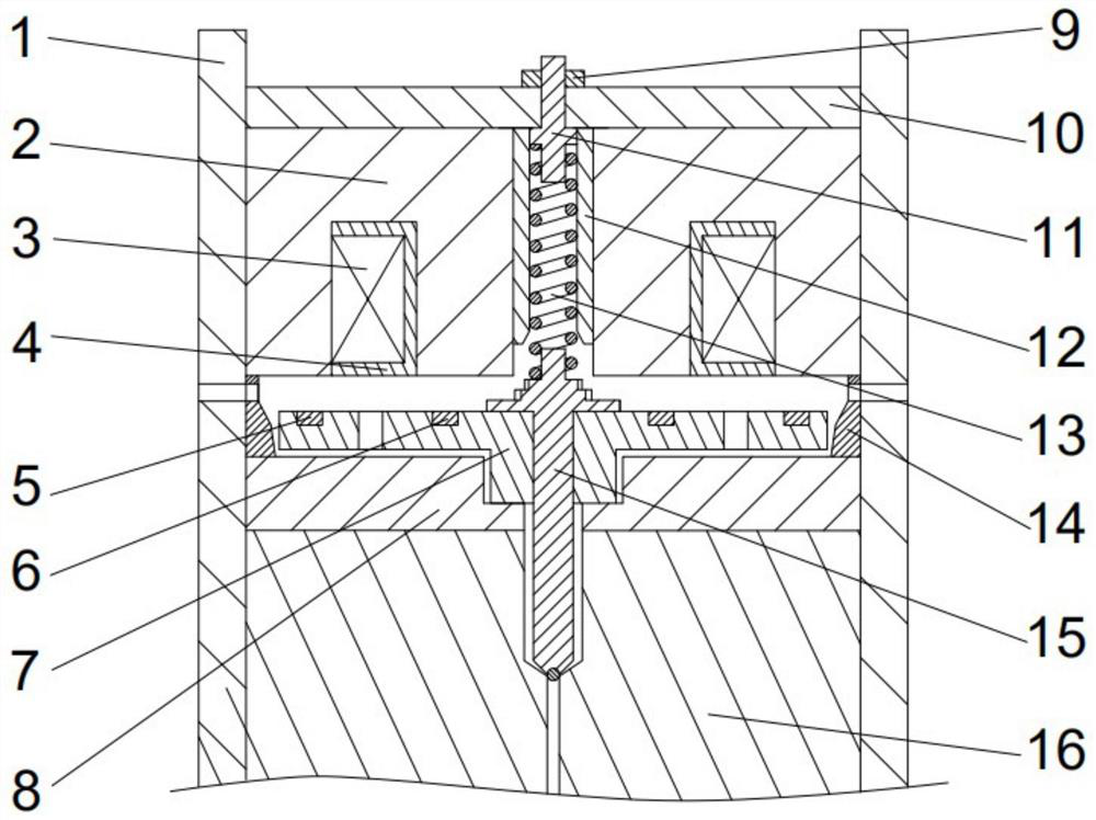
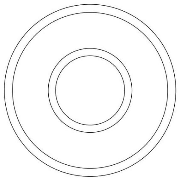
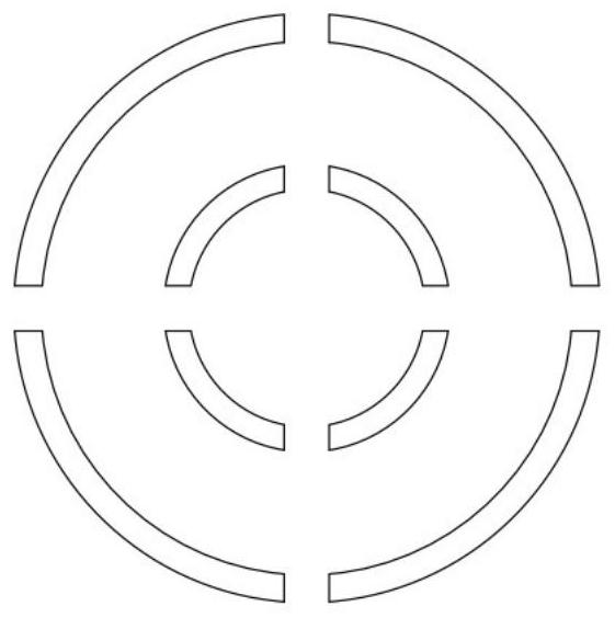
[0026] combine Figure 1-5 The composition of the present invention includes a housing 1, an iron core 2, a coil 3, a coil bobbin 4, an outer permanent magnet ring 5, an inner permanent magnet ring 6, an armature 7, an armature buffer seat 8, an adjusting nut 9, a fixing nut 10, a cross Type bolt 11, spring guide sleeve 12, armature return spring 13, armature lift adjustment ring 14, valve stem 15, injector body 16. The top of the housing 1 is provided with a fixing nut 10, and the iron core 2 is provided with an annular groove to form the main magnetic pole 18 and the auxiliary magnetic pole 20 of the iron core. The width and axial height of the groove are equal to or less than the depth of the annular groove of the iron core. The coil bobbin 4 is embedded in the annular groove of the iron core. There is an axial center through hole in the middle of the iron cor...


PUM


Abstract

The electromagnetic-permanent magnet multi-magnetic field composite high-speed electromagnetic valve comprises a shell and an iron core, an annular groove is formed in the iron core, a coil is wound in a coil framework, the coil framework and the coil framework are embedded into the annular groove of the iron core, an armature is provided with an outer permanent magnet ring and an inner permanent magnet ring, and the outer permanent magnet ring and the inner permanent magnet ring are embedded into the upper portion of the armature. The magnetizing directions of the two permanent magnet rings are both axial radiation magnetizing but the polarities are opposite, a buffering boss is arranged on the head portion of the valve rod, a buffering seat is arranged between the armature and the oil sprayer body, and the armature lift adjusting ring is provided with a radial oil outlet hole. The problems that an existing high-speed electromagnetic valve is low in dynamic response and large in rebound degree during armature attraction and seating are solved through the technical means of cooperative coupling excitation of the inner permanent magnet ring, the outer permanent magnet ring and the electrified coil, throttling damping between a stepped buffering boss at the head of the valve rod and the inner wall of the iron core, throttling damping between the lower surface of the center of the armature and the upper surface of the buffering seat and the like. And the oil injection stability of the high-pressure common-rail oil injector is improved.

Description

technical field [0001] The invention relates to a diesel engine, in particular to a high-pressure common rail device for a diesel engine. Background technique [0002] The high-pressure common rail system is one of the core systems for modern diesel engines to achieve energy saving and emission reduction due to its higher fuel injection pressure and more flexible and controllable cycle fuel injection volume. The high-speed solenoid valve is the key control component of the high-pressure common rail injector. The essence of the control system to control the cycle injection volume, injection timing and injection law of the common rail injector is to control the high-speed solenoid valve inside the injector. actuator control. In order to meet higher practical application requirements, conventional high-speed solenoid valves use higher drive voltages to generate large currents to accelerate their lifting speed during the opening phase, which leads to the fact that the armature ...

Claims


Application Information

Patent Timeline
Patent Type & Authority Applications(China)
IPC IPC(8): F02M63/00F02M63/02
CPCF02M63/0021F02M63/0225
Inventor 赵建辉卢相东张恒徐煜郭楠
Owner HARBIN ENG UNIV
Why Eureka
Try Eureka