
Defrosting device for refrigeration equipment

A technology of refrigeration equipment and cavity placement, which is applied to household refrigeration equipment, lighting and heating equipment, defrosting, etc., which can solve the problems of inconvenient maintenance, inability to use, and lack of defrosting function, and achieve the effect of easy maintenance and low cost

Active Publication Date: 2021-01-12
绍兴市上虞区武汉理工大学高等研究院
View PDF7 Cites 0 Cited by
  • Summary
  • Abstract
  • Description
  • Claims
  • Application Information

AI Technical Summary

Problems solved by technology

[0005] In view of this, it is necessary to provide a defrosting device for refrigeration equipment to solve the problem that the existing defrosting equipment is fixedly installed in the refrigerator, which is inconvenient to maintain and cannot be applied to refrigerators without defrosting function.

Method used


Image

  • Defrosting device for refrigeration equipment
  • Defrosting device for refrigeration equipment
  • Defrosting device for refrigeration equipment

Examples


Embodiment 1

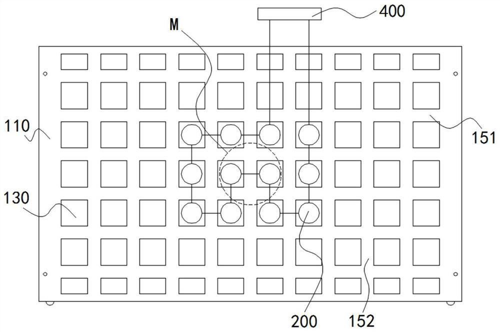
[0045]Such asimage 3 As shown, a plurality of electric heating devices 200 are concentrated at the center of the cover 120, that is, at the air outlet of the air supply assembly 300. The area where the air supply assembly 300 blows into the air guide gap 140 is the area M. When the assembly 300 blows air, the air entering the air guide gap 140 is directly heated by a plurality of electric heating devices 200, and hits the connecting plate 110, and diffuses from the area M to the surroundings.

Embodiment 2

[0047]Such asFigure 7 As shown, a plurality of electric heating devices 200 are arranged along the central circumference of the cover plate 120. When the air blowing assembly 300 blows air, the area where the air blowing assembly 300 blows into the air guiding gap 140 is the area M and enters the air guiding gap 140 The air hits the connecting plate 110 and diffuses from the area M to the surroundings. The air diffused to the surroundings is heated by a plurality of electric heating devices 200.

Embodiment 3

[0049]Such asFigure 8 As shown, a plurality of electric heating devices 200 are centrally arranged and arranged staggered from the air outlet of the air supply assembly 300. When the air supply assembly 300 delivers air, the area where the air supply assembly 300 blows into the air guide gap 140 is the area M. The air entering the air guide gap 140 hits the connecting plate 110, and the air flow diffused from the area M to the surroundings, only one direction of air flow will be heated by the multiple electric heating devices 200, and the air flow in the other directions will be directly discharged from the air guide gap 140 .

[0050]It can be understood that the arrangement of the plurality of electric heating devices 200 is not limited to the arrangement of the above three embodiments. For example, some of the electric heating devices 200 are all facing the air outlet of the air supply assembly 300, and the other The electric heating device 200 and the air outlet of the air blowing ...


PUM


Abstract

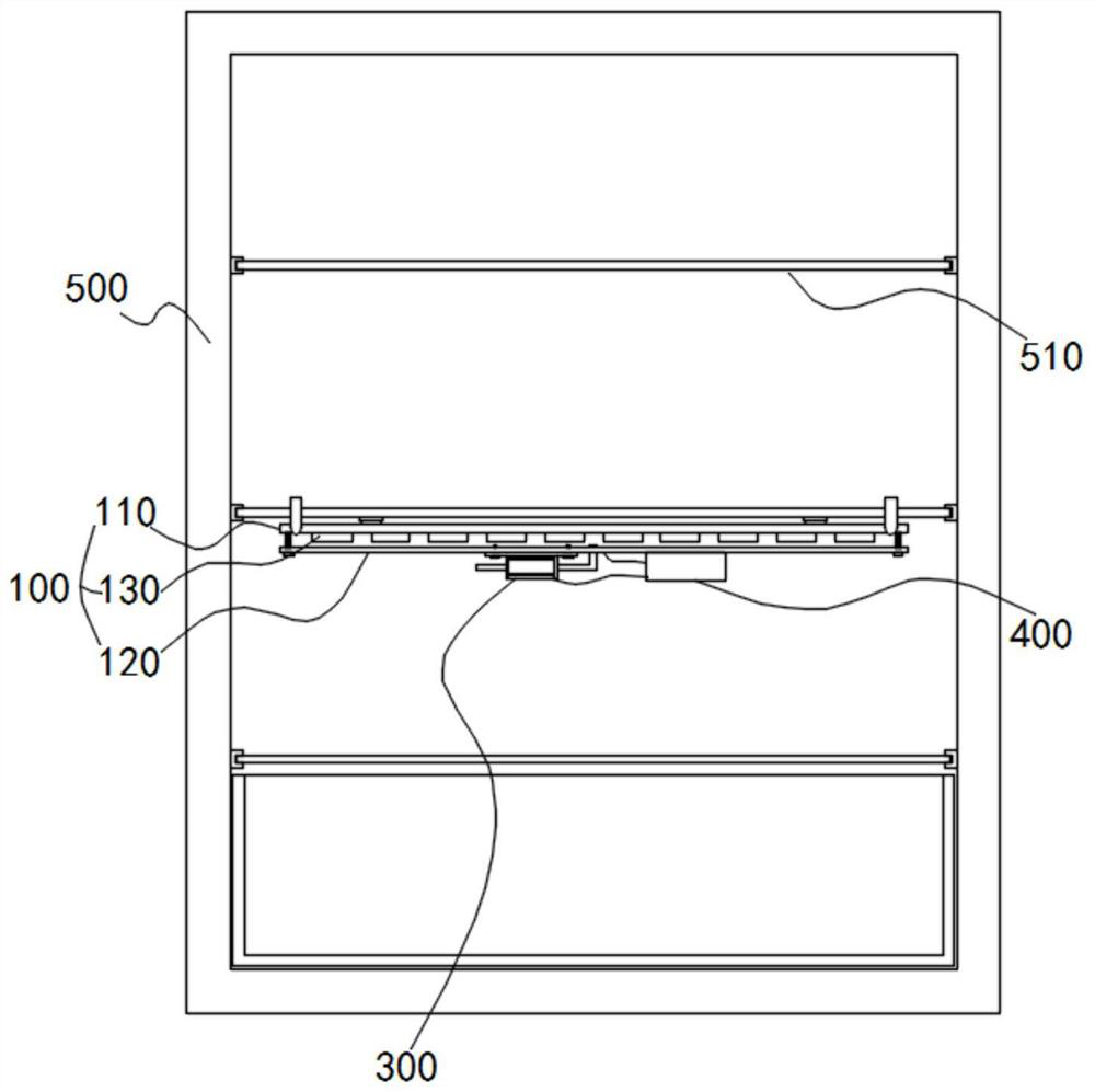
The invention relates to a defrosting device for refrigeration equipment. The defrosting device comprises an air outlet plate, a plurality of electric heating devices, an air supply component, a powersource and a connecting piece, wherein the air outlet plate comprises a connecting plate, a cover plate parallel to the connecting plate and a plurality of heating boxes, the plurality of heating boxes are arranged between the connecting plate and the cover plate, and each heating box is internally provided with a placing cavity; the plurality of electric heating devices are respectively arrangedin the different placing cavities; the air supply component is fixedly connected to the cover plate, an air outlet of the air supply component vertically points to the center of the cover plate, andthe air outlet of the air supply component is communicated with an air guide gap arranged between the connecting plate and the cover plate, so that air can be discharged from the air guide gap in thecircumferential direction; the power source is electrically connected to the plurality of electric heating devices; and the problems that existing defrosting equipment is fixedly arranged in a refrigerator, is inconvenient to maintain and cannot be applied to the refrigerator without a defrosting function are solved.

Description

Technical field[0001]The invention relates to the technical field of refrigeration equipment, in particular to a defrosting device for refrigeration equipment.Background technique[0002]Refrigerator is a kind of refrigeration equipment that can maintain a constant low temperature, and it is also a civilian product that keeps food or other items in a constant low temperature and cold state.[0003]When the refrigerator is in use, the inner wall of the refrigerator is prone to frost, which hinders the heat exchange between the air in the refrigerator and the cold air around the refrigeration pipe, which reduces the refrigeration effect, which not only increases the power consumption of the refrigerator, but also reduces the refrigeration effect.[0004]In order to solve the above frosting problem, some refrigerators on the market currently have defrosting function, but the defrosting equipment is fixedly installed in the refrigerator, which is inconvenient to maintain, and this kind of def...

Claims


Application Information

Patent Timeline
Patent Type & Authority Applications(China)
IPC IPC(8): F25D21/08F25D21/12
CPCF25D21/08F25D21/125Y02P60/85
Inventor 范晓庆刘博张佩玉郭玲琼
Owner 绍兴市上虞区武汉理工大学高等研究院
Learn More