
Heat dissipation structure and power distribution control cabinet with heat dissipation function

A technology of heat dissipation structure and control cabinet, applied in substation/distribution device casing, electrical components, substation/switch layout details, etc., can solve the problems of heat accumulation of electrical equipment and affect normal work, so as to improve heat dissipation efficiency and ensure heat conduction. The effect of heat dissipation

Inactive Publication Date: 2021-01-29
张仲丰
View PDF0 Cites 0 Cited by
  • Summary
  • Abstract
  • Description
  • Claims
  • Application Information

AI Technical Summary

Problems solved by technology

[0004] The purpose of the embodiment of the present invention is to provide a heat dissipation structure to solve the problem that the existing power distribution control cabinet proposed in the above background technology easily leads to the accumulation of heat generated by the electrical equipment itself and affects its normal operation

Method used


Image

  • Heat dissipation structure and power distribution control cabinet with heat dissipation function
  • Heat dissipation structure and power distribution control cabinet with heat dissipation function
  • Heat dissipation structure and power distribution control cabinet with heat dissipation function

Examples


Embodiment Construction

[0019] In order to make the technical problems, technical solutions and beneficial effects to be solved by the present invention clearer, the present invention will be further described in detail below in conjunction with the accompanying drawings and embodiments. It should be understood that the specific embodiments described here are only used to explain the present invention, not to limit the present invention.

[0020] In describing the present invention, it should be understood that the terms "upper", "lower", "front", "rear", "left", "right", "top", "bottom", "inner", " The orientation or positional relationship indicated by "outside", etc. is based on the orientation or positional relationship shown in the drawings, and is only for the convenience of describing the present invention and simplifying the description, rather than indicating or implying that the referred device or element must have a specific orientation, so as to Specific orientation configurations and ope...


PUM


Abstract

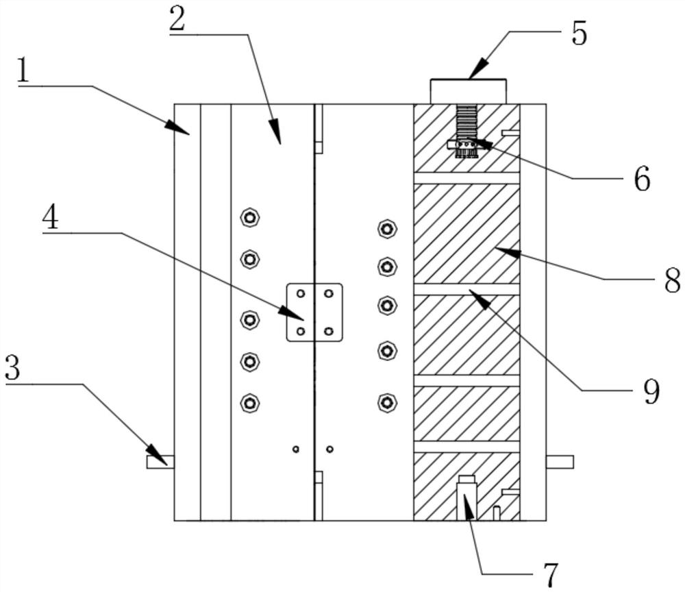
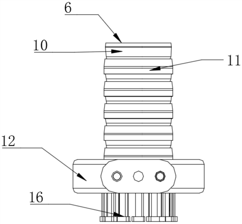
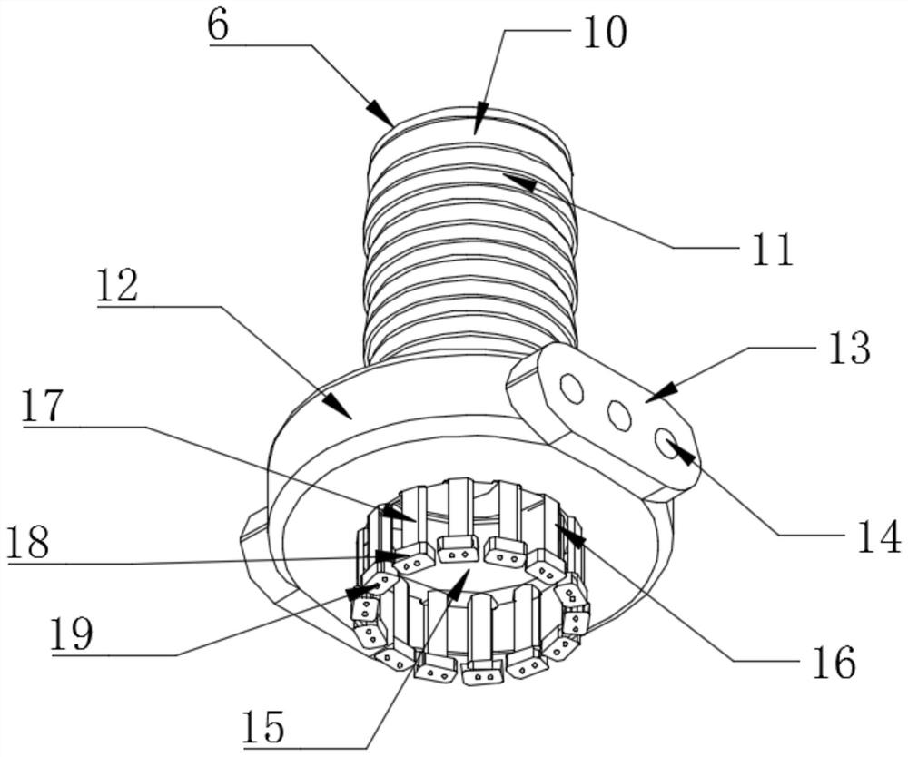
The invention is applicable to the technical field of power distribution control cabinets, and provides a heat dissipation structure and a power distribution control cabinet with a heat dissipation function, the heat dissipation structure comprises a cabinet body, a movable sealing door and a plurality of groups of heat insulation plates, two adjacent heat insulation plates form a heat dissipationchannel, and a heat dissipation part is arranged in the cabinet body. The heat dissipation part comprises a communication port, a mounting base and a plurality of spiral heat conduction pipes, the heat conduction pipes jointly form a cavity, one end of each heat conduction pipe is connected with the heat dissipation part, and an air source mechanism is arranged on the outer side of the cabinet body. The heat dissipation medium is input through the air source mechanism so that the heat dissipation part can convey the heat dissipation medium into the cabinet body through the heat dissipation channel for heat dissipation, the heat conduction and heat dissipation effect of the heat dissipation part can be guaranteed through the heat conduction pipe on the basis of occupying small space, and meanwhile the heat dissipation part is matched with the cavity for conveying the heat dissipation medium for heat dissipation. The heat dissipation efficiency is effectively improved, and the problem that an existing power distribution control cabinet easily causes heat accumulation generated in the working process of electrical equipment and influences normal work of the electrical equipment is solved.

Description

technical field [0001] The invention belongs to the technical field of power distribution control cabinets, in particular to a heat dissipation structure and a power distribution control cabinet with heat dissipation function. Background technique [0002] Currently on the market, the power distribution control cabinet is a common accommodation device used to integrate various electrical equipment to achieve multiple functions. The power distribution control cabinet used usually has the function of measuring and protecting the normal operation of electrical equipment to meet the requirements of the normal operation of the power system. Therefore, most power distribution control cabinets are closed or semi-closed metal cabinets. [0003] At present, most of the traditional power distribution control cabinets are closed or semi-closed metal cabinets, but the above-mentioned technical solutions still have the following shortcomings in actual use: the existing power distributio...

Claims


Application Information

Patent Timeline
Patent Type & Authority Applications(China)
IPC IPC(8): H02B1/30H02B1/56H02B1/28
CPCH02B1/28H02B1/30H02B1/565
Inventor 张仲丰
Owner 张仲丰
Learn More