electrical connector

A technology of electrical connectors and socket connectors, which is applied in the direction of connection, parts and circuits of connection devices, which can solve the problems of enlarging the shape of the housing and achieve the effects of avoiding enlargement, ensuring rigidity, and preventing misfitting

Active Publication Date: 2022-04-05
FUJIKURA LTD
View PDF17 Cites 0 Cited by
  • Summary
  • Abstract
  • Description
  • Claims
  • Application Information

AI Technical Summary

Problems solved by technology

In order to prevent this, in order to obtain a predetermined strength even if the key groove is formed, it is necessary to set the thickness of the case on the side where the key groove is formed to be thicker from the beginning, but in this case the outer shape of the case becomes larger, which Runs counter to the purpose of miniaturizing electrical connectors

Method used


Image

  • electrical connector
  • electrical connector
  • electrical connector

Examples


Embodiment Construction

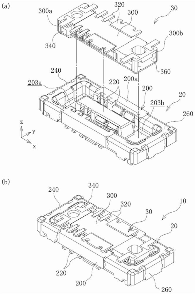
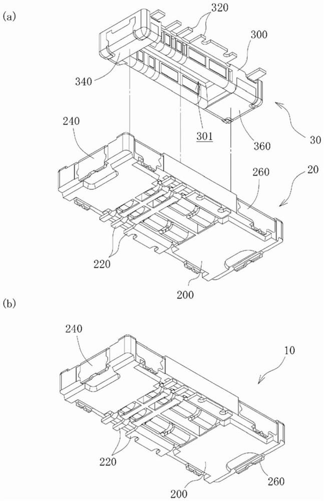
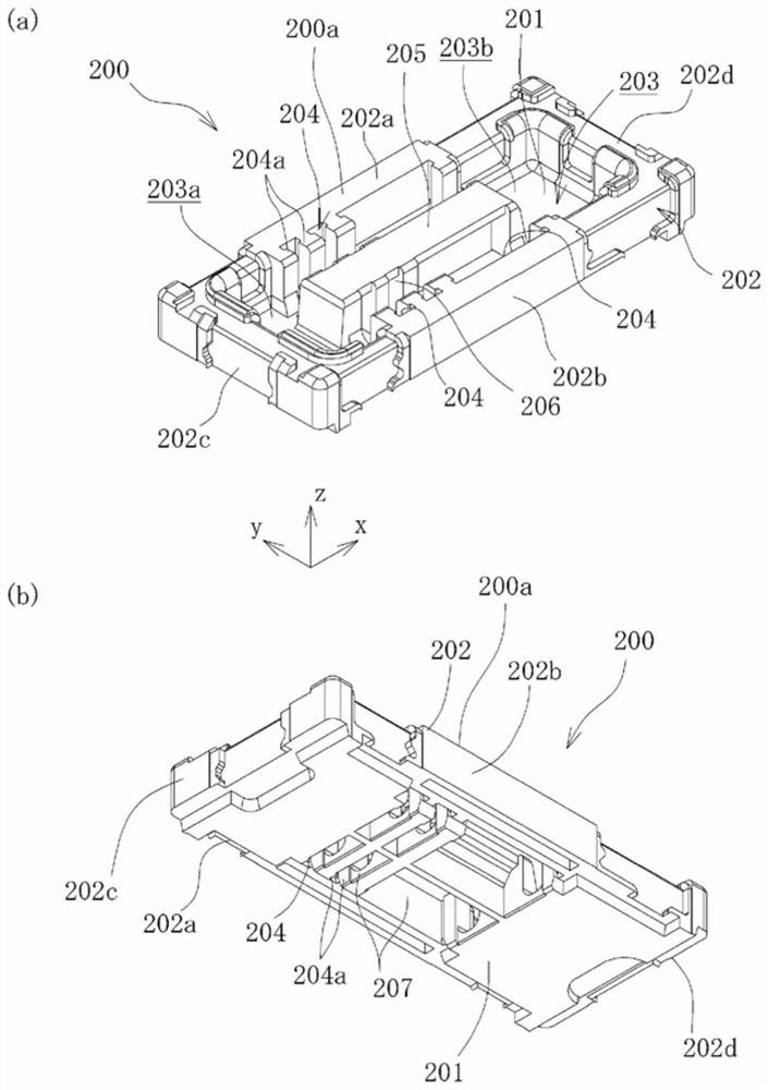
[0031] Hereinafter, embodiments of the electrical connector of the present invention will be described in detail based on the drawings. An electrical connector according to one embodiment of the present invention is a board-to-board connector, including a receptacle connector and a plug connector respectively mounted on two boards (not shown), and the receptacle connector and the plug connector are connected to each other. Connect to electrically connect the two substrates. The type and form of the substrate are not particularly limited as long as it can be mounted on a receptacle connector or a plug connector. For example, it may be a rigid substrate, a flexible substrate (FPC), a rigid flexible substrate (rigid FPC substrate), or the like. In the following description, the bottom surface or the lower surface of the receptacle connector and the plug connector refer to the surface mounted on the substrate, respectively, and the upper surface refers to the surface opposite to t...


PUM


Abstract

An electrical connector according to the present invention includes a plug connector (30) and a socket connector (20). The socket connector (20) has a first housing (200) and a required number of first contacts (220), and the first housing (200) has a first recessed part (203a) and a second recessed part (203b). The first recessed part (203a) and the second recessed part (203b) have shapes different from each other. The receptacle connector (20) has: a metal first cover (240), which covers the part of the peripheral wall (202) of the first housing (200) that defines the first recessed part (203a); and a metal second cover (240). The second cover (260), which covers the part of the peripheral wall (202) that divides the second recessed part (203b).

Description

technical field [0001] The present invention relates to an electrical connector including a plug connector and a receptacle connector which are detachably fitted to each other. Background technique [0002] Conventionally, as such an electrical connector, there is an electrical connector in which a receptacle connector has an electrically insulating housing in which recessed fitting portions are respectively formed at both ends in the longitudinal direction of a recess portion defined by a peripheral wall and a bottom wall. , and a required number of contacts juxtaposed and held between the recessed parts of the housing, the plug connector has a housing and a required number of contacts juxtaposed and held between the male and female parts of the housing For the contacts, the housing of the plug connector has protrusions formed at both ends in the longitudinal direction and inserted into the recesses of the receptacle connector (for example, refer to Patent Document 1). [...

Claims


Application Information

Patent Timeline
Patent Type & Authority Patents(China)
IPC IPC(8): H01R13/64H01R12/71
CPCH01R13/64H01R12/73H01R13/20H01R12/7005H01R12/716H01R13/5045H01R13/629H01R43/16
Inventor 山田清孝菅谷聪一武井一统
Owner FUJIKURA LTD
Why Eureka
Try Eureka