Connector

A connector, electrical connection technology, applied in the direction of connection, flexible/rotatable wire connectors, parts of connecting devices, etc., can solve the problems of decreased production efficiency, deterioration of work efficiency, increased tension, etc.

Inactive Publication Date: 2004-03-24
HOSIDEN CORP
View PDF0 Cites 0 Cited by
  • Summary
  • Abstract
  • Description
  • Claims
  • Application Information

AI Technical Summary

Problems solved by technology

However, since the insertion direction of the connector metal piece is generally perpendicular to the length direction of the wire when crimping is used, when the connector main body accommodated in the hinge portion rotates around the rotation axis along the direction of the connector plug along with the hinge portion When turning, the extended part of the wire rotates greatly, so when the front end of the wire is fixed on another circuit board by soldering, the wire will be bent excessively and the tension will be increased, which may cause the wire to break or cause damage. The wire prevents the rotation of the hinge
[0004] In addition, in order to avoid the trouble of the aforementioned wire insertion work, in the case of using a connector having a plurality of connector metal parts on the above-mentioned base body for the hinge part, the electrical connection between the connector metal parts and the wires connected to the circuit board When the structure of surface mounting and terminal penetration is made, the work efficiency of fixing and welding will be deteriorated, and the production efficiency will be reduced.
In addition, in the case of a plurality of connector metal parts, this operation must be performed separately, further deteriorating work efficiency

Method used


Image

  • Connector
  • Connector
  • Connector

Examples


Embodiment Construction

[0036] Embodiments of the present invention will be described below with reference to the drawings.

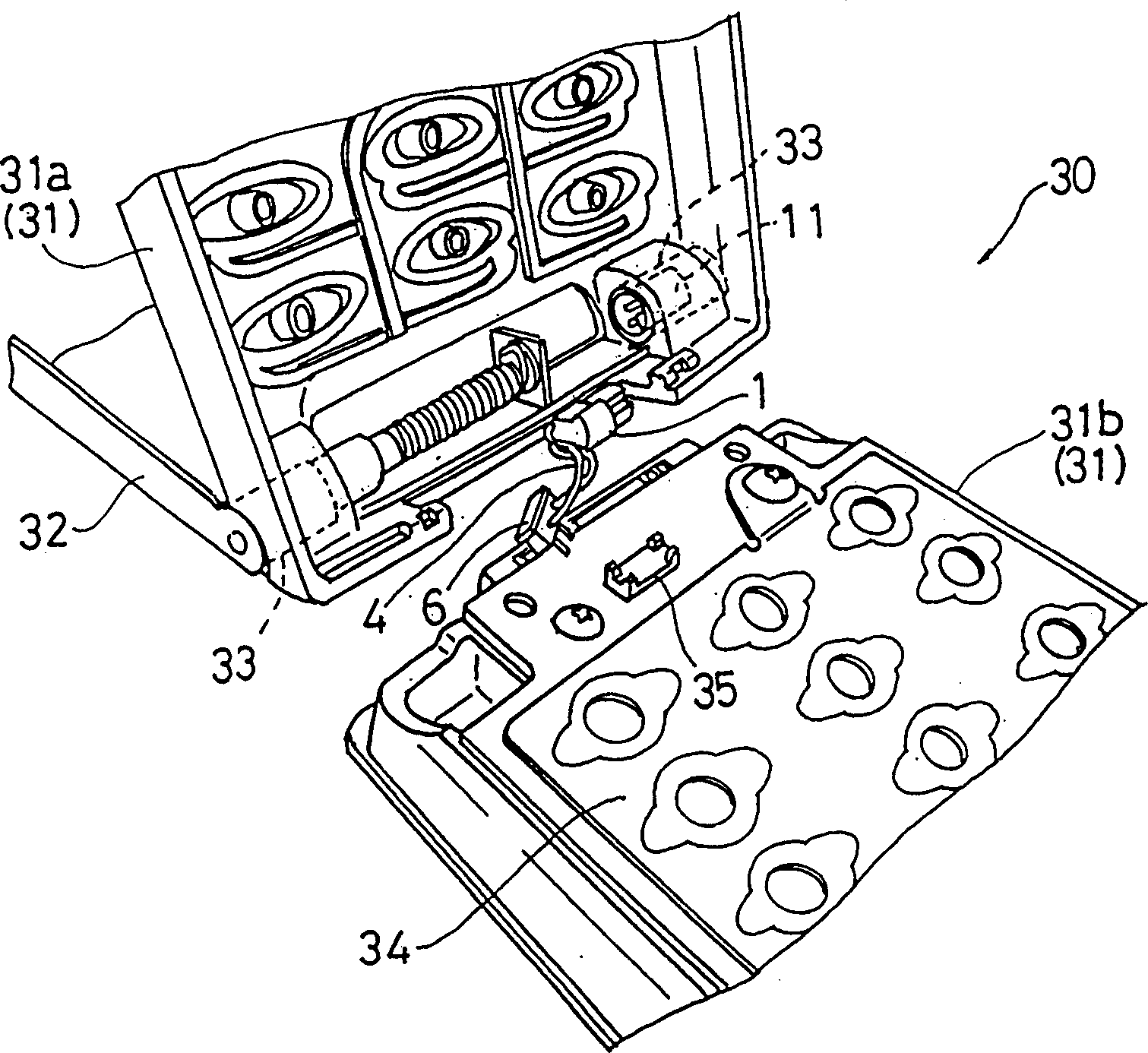
[0037]The connector 1, 11 of the present invention has figure 1 Shown main body 31 and cover 32 are assembled in the female connector 1 of the first characteristic structure of the hinged part of the small apparatus 30 such as mobile phone that can rotate around hinge shaft 33 and constitute, and have the female connector that can be connected with this female connector. 1. The male connector 11 of the second characteristic structure made by fitting. exist figure 1 In the drawing, the main body 31 is disassembled into a cover portion 31 a located on the side of the cover 32 and a board-side main body 31 b accommodating the printed circuit board 34 .

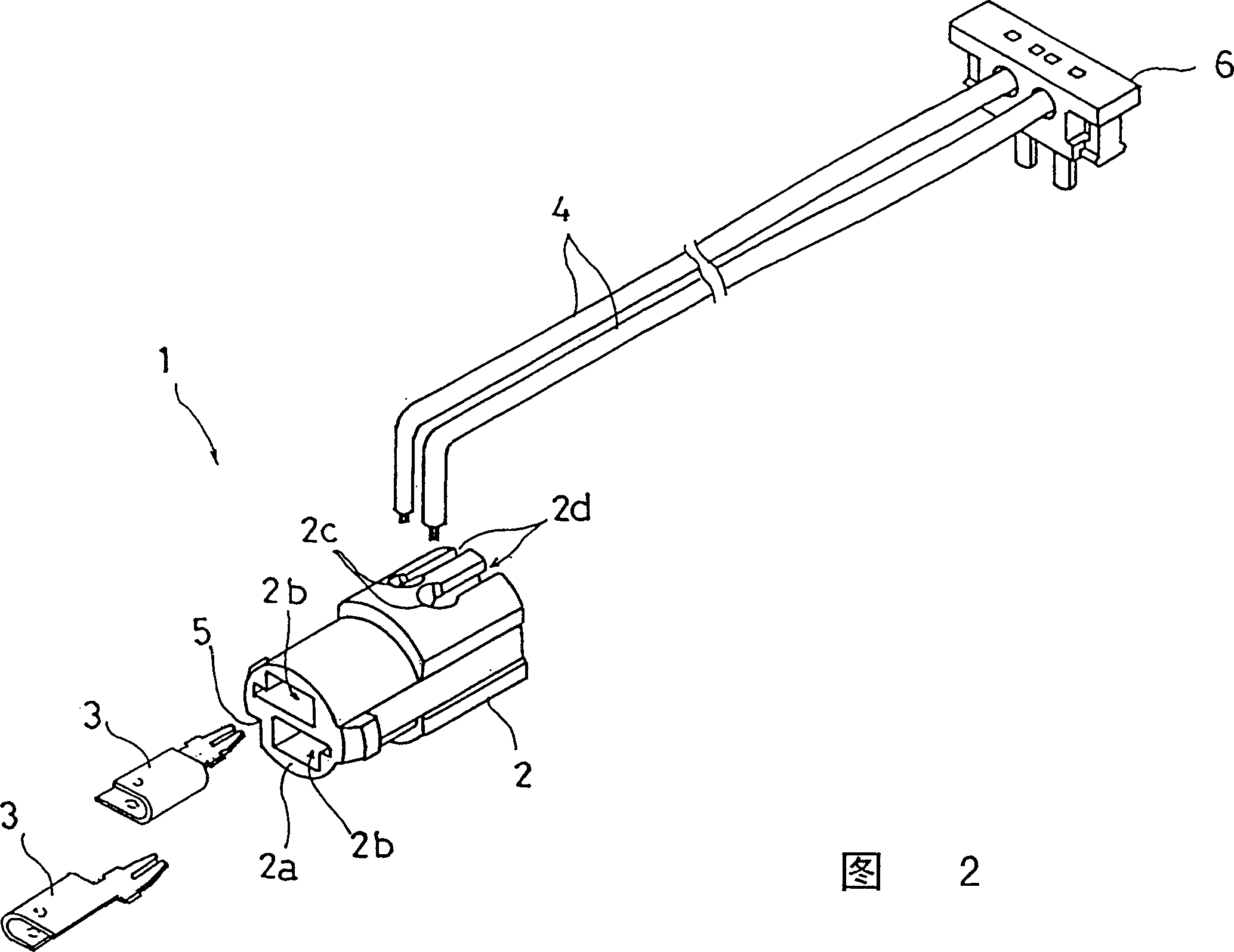
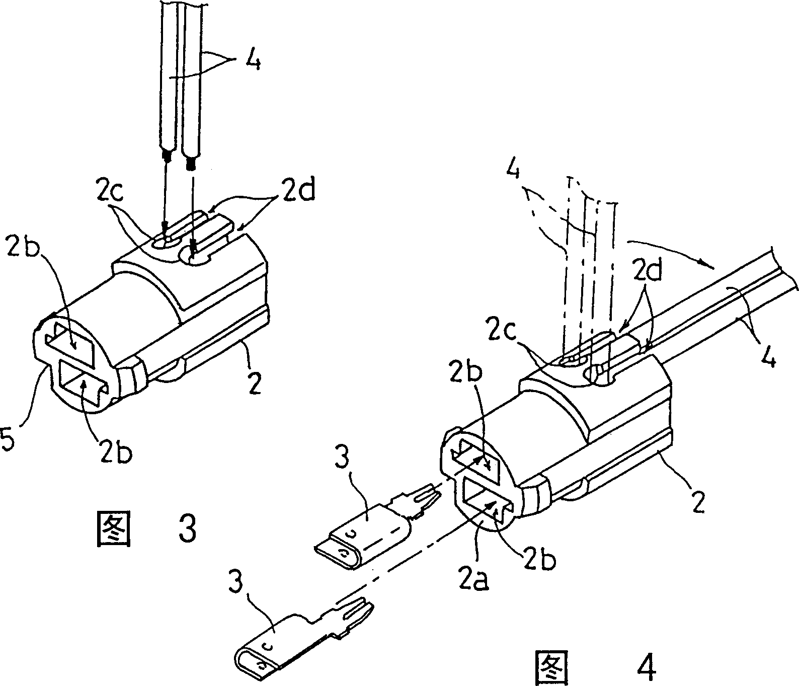
[0038] First, an embodiment of the aforementioned female connector 1 will be described.

[0039] Aforesaid connector 1, as mentioned above, is used in the aforementioned hinged part for being assembled into aforementioned smal...


PUM


Abstract

A connector includes a body, at least one contact metal element inserted and fitted along a direction in the body and a lead wire having one end portion thereof inserted into an opening of the body along a further direction different from the inserting direction of the contact metal element. The one end portion of the lead wire inserted in the body is laterally pressed and contacted by a leading end of the contact metal element to be electrically connected therewith, and the other portion of the lead wire not inserted in the body is bent at the opening to the inserting direction of the contact metal element, with the bent portion of the lead wire being retained by a lead wire retaining portion of the body. (2) A connector includes a body and a plurality of contact metal elements inserted and fitted in the body. One-side ends of the contact metal elements project respectively from a front face of the body in a first direction facing the front face and the other-side ends of the contact elements extend parallel with each other relative to the first direction and along an outer peripheral side face of the body in a second direction normal to the first direction. A gap of a predetermined distance is formed between all the other-side ends of the contact elements and the outer peripheral side face.

Description

technical field [0001] The invention relates to a connector provided with a connector metal part on a base body and a wire electrically conducting with the metal part, and a connector equipped with a plurality of connector metal parts on the base body. More specifically, it relates to a connector suitable for connecting an electric circuit on the main body side to an electric circuit on the cover side in a small device such as a mobile phone in which the main body and the cover are rotatable about a hinge axis. Background technique [0002] Heretofore, in a small device 40 such as a mobile phone in which the main body 41 and the cover 42 shown in FIG. The wire 44 has to be inserted into the hinge. However, such lead wire insertion work interferes with automatic assembly, and becomes a factor that reduces work efficiency. [0003] In addition, using the above-mentioned connector equipped with a connector metal part on the base body and a wire for electrically conducting the...

Claims


Application Information

Patent Timeline
Patent Type & Authority Patents(China)
IPC IPC(8): H01R31/06H01R35/02H04M1/02
CPCH04M1/0216H01R35/02H01R31/06
Inventor 长田孝之
Owner HOSIDEN CORP
Why Eureka
Try Eureka