Metal product discharge device and metal product manufacturing method
A technology of metal products and discharge devices, applied in the direction of pushing out equipment, etc., can solve problems such as the influence of the formation of laminated iron cores, and achieve the effect of inhibiting the return
- Summary
- Abstract
- Description
- Claims
- Application Information
AI Technical Summary
Problems solved by technology
Method used
Image

Examples
example 1
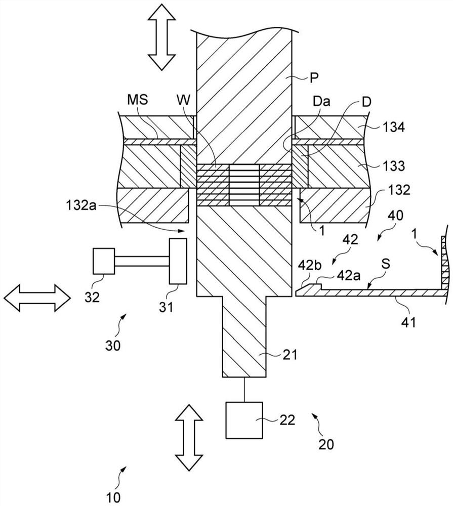
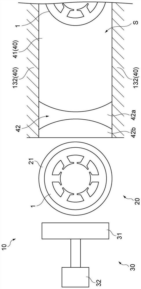
[0076] Example 1. A discharge device (10) for a metal product according to an example of the present invention includes: a support portion (20) for holding a metal product (1 ) is supported; the unloading path (40) is configured to unload the metal product (1); and the push rod (30) is configured to push out the metal product (1) supported by the support portion (20) to the unloading path . The bottom (41) of the carry-out path (40) includes a protruding portion (42) protruding upward from the bottom surface (S). The protruding part (42) is arranged at the upstream end of the carry-out path (40) or in the middle of the carry-out path, and is configured so that the metal product (1) pushed out to the carry-out path (40) by the push rod (30) can pass over. In this case, the metal product pushed out by the push rod until it passes over the protruding part is not easy to return to the support part side due to the protruding part. Therefore, it is possible to suppress the return ...
example 7
[0082] Example 7. A discharge device (10) for a metal product according to another example of the present invention includes: a support portion (20) for holding a metal product (1 ) is supported; the unloading path (40) is configured to unload the metal product (1); and the push rod (30) is configured to push out the metal product (1) supported by the support portion (20) to the unloading path (40). The unloading path (40) includes an opening and closing portion (43) configured to be able to change between a closed state and an open state, and the closed state means that the opening and closing portion (43) is pushed out into the unloading path (40) to block the metal product. (1) The state of passing, the open state refers to the state in which the opening and closing part (43) withdraws from the carry-out path (40) and allows the metal product (1) to pass through. The opening and closing unit (43) is arranged at the upstream end portion of the carrying out path (40) or at t...
example 12
[0087] Example 12. The method of manufacturing a metal product according to another example of the present invention includes: punching a metal plate with a die to form a metal product on a support portion; The supported metal product is pushed out to the carry-out path from the supporting portion, and the protruding portion protrudes upward from the bottom surface of the carry-out path, and is arranged at an upstream end portion of the carry-out path or a middle portion of the carry-out path.
[0088] In this case, the same effect as in Example 1 is obtained.
PUM
 Abstract
Description
Claims
Application Information
 - R&D Engineer
- R&D Manager
- IP Professional
- Industry Leading Data Capabilities
- Powerful AI technology
- Patent DNA Extraction
Browse by: Latest US Patents, China's latest patents, Technical Efficacy Thesaurus, Application Domain, Technology Topic.
© 2024 PatSnap. All rights reserved.Legal|Privacy policy|Modern Slavery Act Transparency Statement|Sitemap