A pull-type window breaking device

A pull-type, window-breaking technology, applied in building rescue, life-saving equipment, etc., can solve the problems of hard-to-break tempered glass, hard-to-reach, unsuitable car windows, etc., and achieve the effect of easy grasping and use

Active Publication Date: 2022-02-01
CHONGQING PUBLIC TRANSPORTATION CAREER ACADEMY
View PDF15 Cites 0 Cited by
  • Summary
  • Abstract
  • Description
  • Claims
  • Application Information

AI Technical Summary

Problems solved by technology

Such as authorized announcement number is CN105999572A "A kind of multi-functional vehicle window breaker", CN206566367U "A kind of window breaker and the device using the breaker", etc., these window breakers provide emergency escape when the bus has an accident Useful tools, but they have a common defect. When danger comes, you need to find a window breaking tool, and because the provided window breaking device is relatively small, and the hardness of the ejection spring is very strong, it is difficult for the elderly and children to use it normally, even adults It is difficult for people to break the tempered glass to escape and save themselves if they are not strong enough or use the wrong method; especially when the vehicle is tilted and overturned at 90 degrees, it is difficult for passengers to get the window breaker. Use a window breaker to knock on the tempered glass placed on top
There is a portable window breaker in the prior art, which is small and portable, but it needs to fire the device to break the window. It is necessary to hold the device and apply a pressure of more than 10 kg in the direction of the tempered glass to achieve the effect of firing the cone head to break the window. purpose, which is still not suitable for small children and the elderly, or with the windows up

Method used


Image

  • A pull-type window breaking device
  • A pull-type window breaking device
  • A pull-type window breaking device

Examples


Embodiment Construction

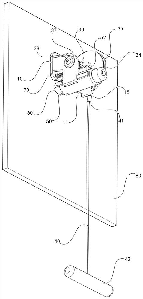
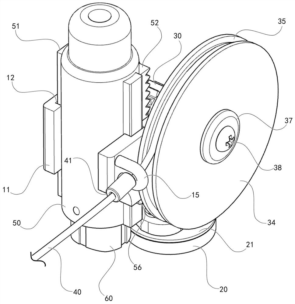
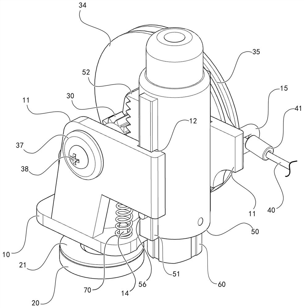
[0018] Below, the present invention will be further described in conjunction with accompanying drawing and embodiment: Figure 1 to Figure 5 As shown, a pull-type window breaking device includes a positioning head 10, a thumb screw 20, an anti-skid washer 21, a moving gear 30, a stay cord 40, a catapult shell 50, an extrusion head 60, and a spring 70; it is characterized in that the The positioning head 10 is provided with a support block 11, and the support block 11 is provided with a chute 12, a shaft hole 13 and a first convex nail 14; The center of the two ends of the shaft of the moving gear 30 is provided with internal threads 31; a screw 38 passes through the cover plate 37, the ferrule 32, and then passes through the shaft hole 13 is screwed into the internal thread 31; one end of the connecting shaft 33 is inserted into the special-shaped hole 36, and the other end is inserted into the rotating shaft hole 13, and another screw 38 is screwed into the internal thread 31...


PUM


Abstract

A pulling type window breaking device, a pulling type window breaking device, comprising a positioning head, a thumb screw, an anti-skid washer, a moving gear, a pull cord, a catapult shell, an extrusion head, and a spring; it is characterized in that the positioning head , is provided with a support block, and the support block is provided with a chute, a shaft hole and a first convex nail; the screw rod of the thumb screw passes through the anti-skid washer and the preset round hole on the tempered glass, and the positioning head is fixed on the tempered glass Above; the center of the two ends of the shaft of the moving gear is provided with threads; a screw passes through the cover plate, the ferrule, and then passes through the shaft hole and screwed into the internal thread; one end of the connecting shaft is inserted into the special-shaped hole, and the other end is inserted into the In the shaft hole, another screw passes through the cover plate and the connecting shaft and screwed into the internal thread; the two screws fix the moving gear, the ferrule, the connecting shaft, the turntable, and the cover plate as a whole, and this whole can be positioned Rotate in the shaft hole on the head. No matter how inclined the vehicle is, the present invention can be conveniently grasped and used to realize broken windows.

Description

technical field [0001] The invention relates to the technical field of window breakers, in particular to a pull-type window breaker. Background technique [0002] Commonly used tools for bus and coach travel. In order to be able to run faster on the highway, the current buses and buses often use a whole piece of tempered window glass. During the long-distance driving of the vehicle, some accidents will inevitably occur. When this type of vehicle burns in the compartment or the vehicle overturns, the passengers in the compartment often need to implement self-rescue in the first time, smash the window glass, and open the escape route to the outside. In order to be easy to escape in an emergency, the current passenger cars are equipped with a window breaker, which can be used to break the window glass to escape when encountering a critical situation. In the event of an accident, passengers must first find the window breaker and have the correct method of breaking the window ...

Claims


Application Information

Patent Timeline
Patent Type & Authority Patents(China)
IPC IPC(8): A62B3/00
CPCA62B3/005
Inventor 欧阳刚李亚萍武斌苏涛
Owner CHONGQING PUBLIC TRANSPORTATION CAREER ACADEMY
Why Eureka
Try Eureka