Door lock structure for electric appliance and cleaning machine applying door lock structure

A technology of door lock structure and electrical appliances, which is applied in the field of cleaning machines, can solve the problems of easy failure, complex door lock action logic, and low reliability, and achieve the effect of simple and reliable process, low requirements for electronic control logic, and easy realization

Pending Publication Date: 2021-03-30
NINGBO FOTILE KITCHEN WARE CO LTD
View PDF1 Cites 5 Cited by
  • Summary
  • Abstract
  • Description
  • Claims
  • Application Information

AI Technical Summary

Problems solved by technology

Although the above structure can lock the door body on the dish washer, its locking structure is complex, highly dependent on electric components and control methods, the logic of the door lock action is complicated, prone to failure, and low in reliability

Method used


Image

  • Door lock structure for electric appliance and cleaning machine applying door lock structure
  • Door lock structure for electric appliance and cleaning machine applying door lock structure
  • Door lock structure for electric appliance and cleaning machine applying door lock structure

Examples


Embodiment Construction

[0048] The present invention will be further described in detail below in conjunction with the accompanying drawings and embodiments.

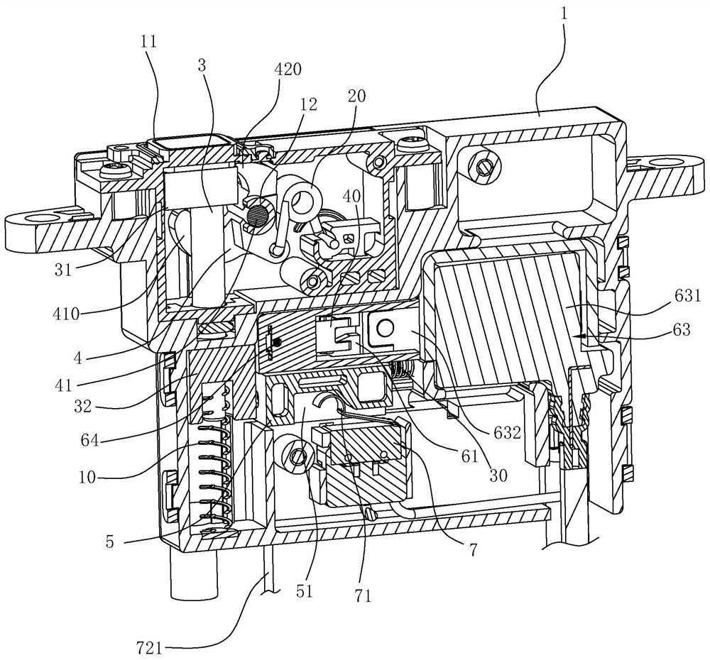
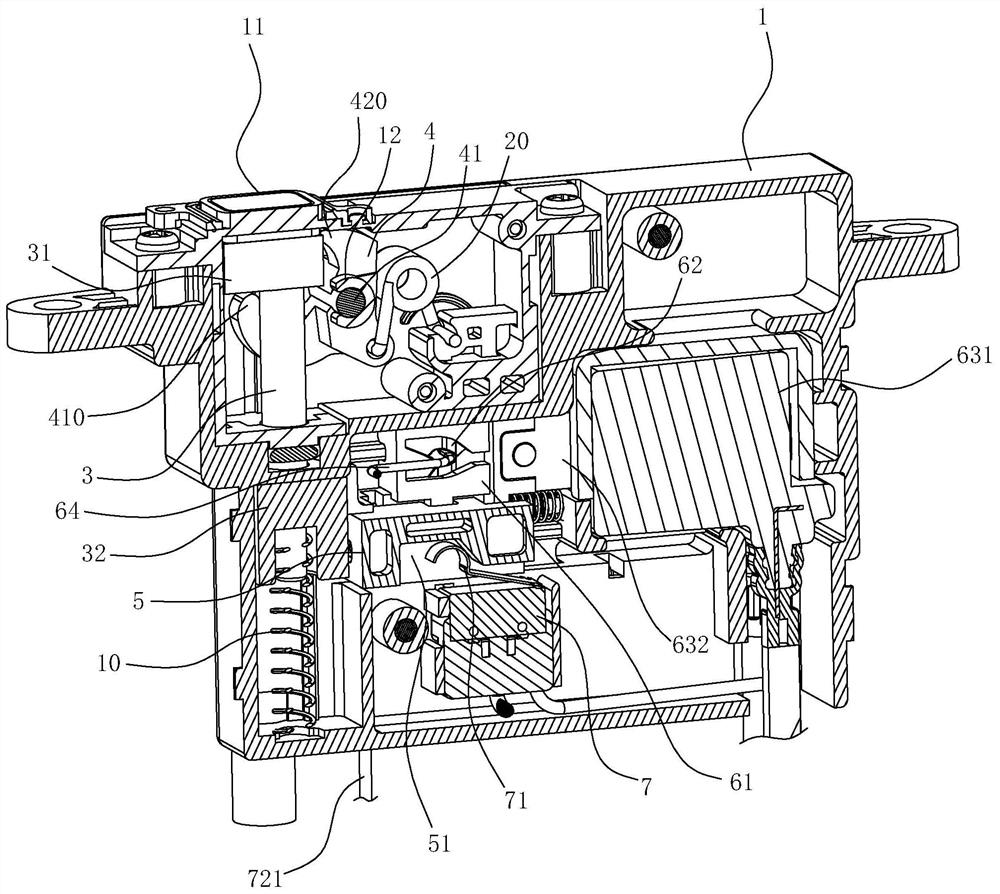
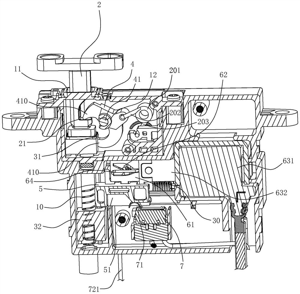
[0049] The door lock structure of this embodiment is used to lock any door body and box body, and this embodiment uses a sink type cleaning machine as an example for illustration. like Figure 11 As shown, the cleaning machine of this embodiment includes a box body 8 and a door body 9, the box body 8 has a washing chamber and an upper port 81 connected to the top of the washing chamber, and an edge of the door body 9 is connected to the upper port of the box body 8 by rotation. 81 at the edge.

[0050] The door lock structure used for electrical appliances in this embodiment includes a housing 1, a lock bar 2, an ejector 3, a lock catch 4, a first elastic member 10, a second elastic member 20, a limit block 5 and a driving mechanism, and the lock bar 2. Installed vertically on the lower wall of the door body 9 and arranged close to the edge,...


PUM


Abstract

The invention relates to a door lock structure for an electric appliance and a cleaning machine applying the door lock structure. The requirement for electric control logic is low, when locking is needed, a lock rod moves downwards and abuts against an ejection piece to move downwards, and in the downward moving process of the ejection piece, the ejection piece drives a lock catch to rotate, so that the upper end of the lock catch is gradually matched with a lock hook and presses the lock hook downwards; a driving mechanism drives a limiting block to move towards the ejection piece and limit the position of the ejection piece, and locking is achieved; when unlocking is needed, the driving mechanism drives the limiting block to move to cancel position constraint on the ejection piece, and at the moment, the lock rod can be driven by a door body to move upwards to achieve unlocking; and the whole process is simple, reliable and convenient to implement.

Description

technical field [0001] The invention relates to a door lock structure for electrical appliances and a washing machine using the door lock structure. Background technique [0002] For a box with a functional inner cavity, due to functional requirements, a door that can open or cover the port is usually provided at the port of the box, and, during the use of the box, it is necessary to place the door relative to the The cabinet is locked. [0003] For example, the Chinese invention patent application "Door Switch Mechanism and Dishwasher with the Door Switch Mechanism" (application publication number: CN1550202A) with application number CN200410043122.5 discloses a structure, which includes: The tableware inlet is configured as a door that can be rotated, and a rotation assist mechanism that applies a rotation assist force to the door along with the rotation of the door; When the door is inside, the door is applied with a rotation assisting force in the direction of closing....

Claims


Application Information

Patent Timeline
Patent Type & Authority Applications(China)
IPC IPC(8): E05B65/00E05B15/00E05B47/00E05F15/611
CPCE05B15/00E05B47/0002E05B65/00E05F15/611
Inventor 林益波王栋朱灯光范文粲王小艳魏瑞晖
Owner NINGBO FOTILE KITCHEN WARE CO LTD
Why Eureka
Try Eureka