Filling, discharging and vacuumizing equipment for argon production

A technology for vacuuming equipment and vacuum tubes, which is applied to equipment loaded into pressure vessels, equipment discharged from pressure vessels, mechanical equipment, etc. It can solve problems such as damage to vacuum pumps, changes in vacuum pump loads, and impact on the service life of vacuum pumps. Improve efficiency, save time and reduce work intensity

Active Publication Date: 2021-04-02
宜春市富锐气体有限责任公司
View PDF8 Cites 2 Cited by
  • Summary
  • Abstract
  • Description
  • Claims
  • Application Information

AI Technical Summary

Problems solved by technology

[0002] In the process of argon production, in order to increase the storage time of argon, it is usually necessary to evacuate the gas in the argon cylinder. The existing evacuation equipment usually connects the vacuum pump to the argon cylinder through a pipeline. After the connection is completed, open the valve switch , the vacuum pump pumps out the gas in the argon gas bottle, but at the moment of opening the valve switch, due to the sudden increase in the load of the vacuum pump, repeated vacuuming, and long-term opening and closing of the valve, the load of the vacuum pump changes, which is easy to cause damage to the vacuum pump. Affect the service life of the vacuum pump

Method used


Image

  • Filling, discharging and vacuumizing equipment for argon production
  • Filling, discharging and vacuumizing equipment for argon production
  • Filling, discharging and vacuumizing equipment for argon production

Examples


Embodiment Construction

[0031] The following will clearly and completely describe the technical solutions in the embodiments of the present invention with reference to the accompanying drawings in the embodiments of the present invention. Obviously, the described embodiments are only some, not all, embodiments of the present invention. Based on the embodiments of the present invention, all other embodiments obtained by persons of ordinary skill in the art without making creative efforts belong to the protection scope of the present invention.

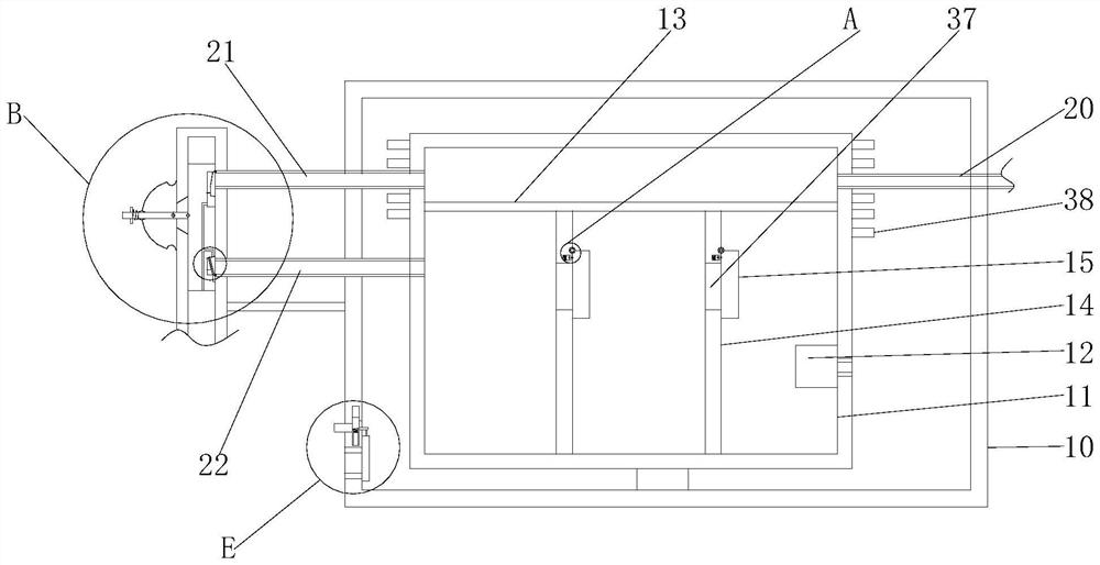
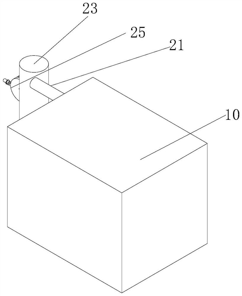
[0032] see Figure 1-8, a filling, discharging and vacuuming equipment produced by argon gas, comprising a casing two 11 and a vacuum pump 12, the vacuum pump 12 is fixedly connected to the casing two 11, the casing two 11 is a hollow cuboid, the vacuum pump 12 and the casing two 11 are right inside The side walls are fixedly connected, a degraded emptying mechanism is set inside the shell two 11, an inflation promotion mechanism and a switching mechanism are ...


PUM


Abstract

The invention relates to the technical field of argon production equipment, and discloses filling, discharging and vacuumizing equipment for argon production. The filling, discharging and vacuumizingequipment for argon production comprises a second shell and a vacuum pump, wherein the vacuum pump is fixedly connected with the second shell; a degradation vacuumizing mechanism is arranged in the second shell; an inflation promoting mechanism and a switching mechanism are arranged outside the second shell; gas in a closed space formed by a first right vertical plate and the second shell is exhausted out of the second shell through a vacuum pump, so that a vacuum environment is formed in the closed space formed by the first right vertical plate and the second shell; gas between the two firstvertical plates pushes a first baffle to turn over so as to drive a first sliding block to slide in a first sliding groove and stretch a first spring, so that gas between the two first vertical platesenters the closed space formed by the first vertical plate on the right side and the second shell; and an argon bottle connected with an argon outlet pipe is separated through the two first verticalplates, so that the situation that the argon bottle suddenly communicates with the vacuum pump, and consequently the load of the vacuum pump is instantly increased is avoided, the vacuum pump is better protected, and the stability of the device is improved.

Description

technical field [0001] The invention relates to the technical field of argon production equipment, in particular to a filling, discharging and vacuuming equipment for argon production. Background technique [0002] In the process of argon production, in order to increase the storage time of argon, it is usually necessary to evacuate the gas in the argon cylinder. The existing evacuation equipment usually connects the vacuum pump to the argon cylinder through a pipeline. After the connection is completed, open the valve switch , the vacuum pump pumps out the gas in the argon gas bottle, but at the moment of opening the valve switch, due to the sudden increase in the load of the vacuum pump, repeated vacuuming, and long-term opening and closing of the valve, the load of the vacuum pump changes, which is easy to cause damage to the vacuum pump. Affect the service life of the vacuum pump. Contents of the invention [0003] (1) Solved technical problems [0004] Aiming at the...

Claims


Application Information

Patent Timeline
Patent Type & Authority Applications(China)
IPC IPC(8): F17C5/06F17C7/00F17C13/00F17C13/04F17C13/06F17C13/08
CPCF17C5/06F17C7/00F17C13/002F17C13/04F17C13/06F17C13/08F17C2201/01F17C2205/0323F17C2205/0352F17C2205/0388F17C2221/016F17C2223/0123F17C2223/038F17C2225/038F17C2227/0114F17C2227/0358F17C2227/045F17C2260/025
Inventor 王勇平
Owner 宜春市富锐气体有限责任公司
Why Eureka
Try Eureka