A kind of filling, filling, draining and vacuuming equipment for argon production

A technology for vacuuming equipment and vacuum tubes, which is applied to equipment loaded into pressure vessels, equipment discharged from pressure vessels, mechanical equipment, etc. It can solve problems such as damage to vacuum pumps, affecting the service life of vacuum pumps, and changes in the load of vacuum pumps. The effect of improving stability

Active Publication Date: 2022-07-19
宜春市富锐气体有限责任公司
View PDF0 Cites 0 Cited by
  • Summary
  • Abstract
  • Description
  • Claims
  • Application Information

AI Technical Summary

Problems solved by technology

[0002] In the process of argon production, in order to increase the storage time of argon, it is usually necessary to evacuate the gas in the argon cylinder. The existing evacuation equipment usually connects the vacuum pump to the argon cylinder through a pipeline. After the connection is completed, open the valve switch , the vacuum pump pumps out the gas in the argon gas bottle, but at the moment of opening the valve switch, due to the sudden increase in the load of the vacuum pump, repeated vacuuming, and long-term opening and closing of the valve, the load of the vacuum pump changes, which is easy to cause damage to the vacuum pump. Affect the service life of the vacuum pump

Method used


Image

  • A kind of filling, filling, draining and vacuuming equipment for argon production
  • A kind of filling, filling, draining and vacuuming equipment for argon production
  • A kind of filling, filling, draining and vacuuming equipment for argon production

Examples


Embodiment Construction

[0031] The technical solutions in the embodiments of the present invention will be clearly and completely described below with reference to the accompanying drawings in the embodiments of the present invention. Obviously, the described embodiments are only a part of the embodiments of the present invention, but not all of the embodiments. Based on the embodiments of the present invention, all other embodiments obtained by those of ordinary skill in the art without creative efforts shall fall within the protection scope of the present invention.

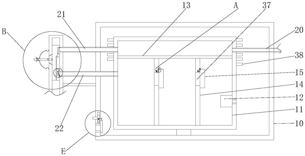
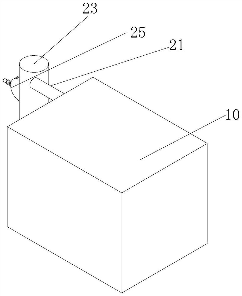
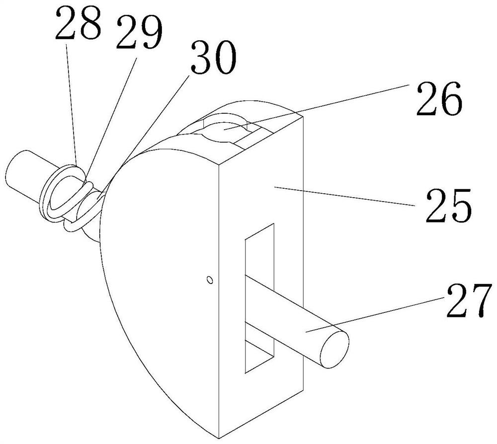
[0032] see Figure 1-8, an argon-produced filling, filling, draining and vacuuming equipment, including a second shell 11 and a vacuum pump 12, the vacuum pump 12 is fixedly connected with the second shell 11, the second shell 11 is a hollow cuboid, and the vacuum pump 12 is connected to the inner right of the second shell 11. The side walls are fixedly connected, a degrading and emptying mechanism is arranged in the second shell 11, ...


PUM


Abstract

The invention relates to the technical field of argon gas production equipment, and discloses a filling, filling, draining and pumping vacuum equipment for argon gas production. , The second outer casing is provided with an inflation promotion mechanism and a switching mechanism, and the gas in the closed space formed by the right vertical plate 1 and the second casing is discharged from the outer casing 2 through a vacuum pump, so that the right vertical plate 1 and the second casing are formed. A vacuum environment is formed in the closed space, and the gas between the two vertical plates 1 pushes the baffle 1 to turn over to drive the slider 1 to slide in the chute 1 and stretch the spring 1, so that the gas between the two vertical plates 1 enters. In the closed space formed by the right vertical plate 1 and the shell 2, the argon cylinder connected to the argon gas outlet pipe is separated by two vertical plates 1, so as to avoid the sudden connection between the argon cylinder and the vacuum pump and increase the load of the vacuum pump instantly, which is better. It can protect the vacuum pump and improve the stability of the device.

Description

technical field [0001] The invention relates to the technical field of argon gas production equipment, in particular to a filling, filling, draining and vacuuming equipment for argon gas production. Background technique [0002] In the argon production process, in order to improve the storage time of argon, it is usually necessary to evacuate the gas in the argon cylinder. The existing evacuation equipment usually connects the vacuum pump to the argon cylinder through a pipeline. After the connection is completed, open the valve switch. , The vacuum pump draws out the gas in the argon bottle, but at the moment when the valve switch is turned on, due to the sudden increase of the load of the vacuum pump, repeated vacuuming and opening and closing the valve for a long time will cause the change of the load of the vacuum pump, which will easily cause damage to the vacuum pump. Affect the service life of the vacuum pump. SUMMARY OF THE INVENTION [0003] (1) Technical problem...

Claims


Application Information

Patent Timeline
Patent Type & Authority Patents(China)
IPC IPC(8): F17C5/06F17C7/00F17C13/00F17C13/04F17C13/06F17C13/08
CPCF17C5/06F17C7/00F17C13/002F17C13/04F17C13/06F17C13/08F17C2201/01F17C2205/0323F17C2205/0352F17C2205/0388F17C2221/016F17C2223/0123F17C2223/038F17C2225/038F17C2227/0114F17C2227/0358F17C2227/045F17C2260/025
Inventor 王勇平
Owner 宜春市富锐气体有限责任公司
Why Eureka
Try Eureka