Cable unwinding equipment for wire and cable manufacturing

A technology of wire and cable unwinding equipment, which is applied in the direction of thin material handling, conveying filamentous materials, transportation and packaging, etc., and can solve the problem of single function of cable unwinding equipment

Active Publication Date: 2022-05-13
深圳市成天泰电缆实业发展有限公司
View PDF9 Cites 0 Cited by
  • Summary
  • Abstract
  • Description
  • Claims
  • Application Information

AI Technical Summary

Problems solved by technology

[0002] Cable unwinding equipment for wire and cable manufacturing is a commonly used equipment in the field of wire and cable manufacturing, but the general function of cable unwinding equipment for wire and cable manufacturing is relatively single

Method used


Image

  • Cable unwinding equipment for wire and cable manufacturing
  • Cable unwinding equipment for wire and cable manufacturing
  • Cable unwinding equipment for wire and cable manufacturing

Examples


specific Embodiment approach 1

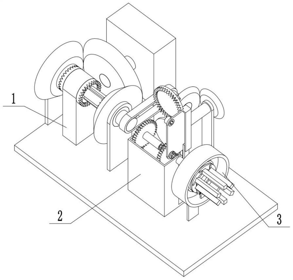
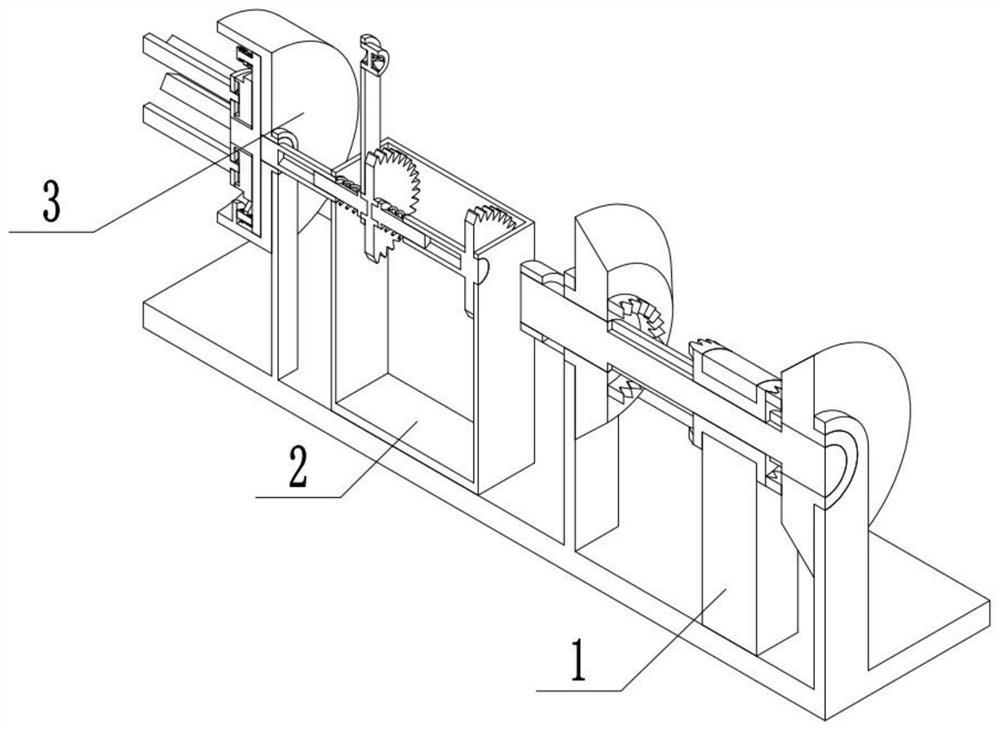
[0028] Combine below Figure 1-11 Describe this embodiment, a cable unwinding device for wire and cable manufacturing, including a drive assembly 1, a switch assembly 2, and a rope winding assembly 3, characterized in that: the drive assembly 1 is connected to the switch assembly 2, and the switch assembly 2 It is connected with the winding rope assembly 3, and the winding rope assembly 3 is connected with the driving assembly 1.

specific Embodiment approach 2

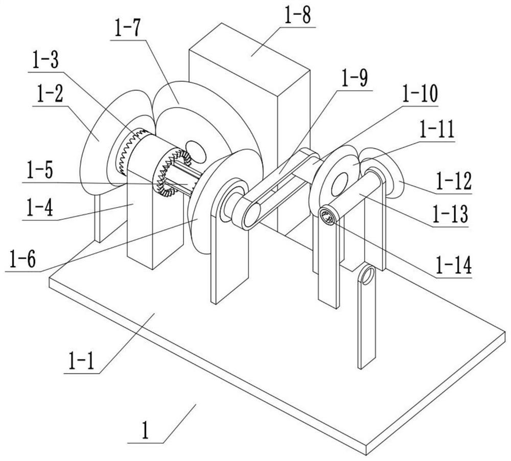
[0029] Combine below Figure 1-11Describe this embodiment, this embodiment will further explain the first embodiment, the drive assembly 1 includes a power base plate 1-1, a bevel gear 1-2, a drive sleeve 1-3, a drive bracket 1-4, and a middle shaft 1-5, bevel gear two 1-6, bevel gear three 1-7, input motor 1-8, belt one 1-9, bevel gear shaft one 1-10, bevel gear four 1-11, bevel gear five 1- 12. Bevel gear shaft 2 1-13, groove 1-14, input motor 1-8 is fixedly connected with power base plate 1-1, middle-end rotating shaft 1-5 is rotationally connected with power base plate 1-1, bevel gear one 1- 2. Bevel teeth 2 1-6 are rotatably connected to the power base plate 1-1, bevel teeth 1 1-2 and bevel 2 1-6 are all rotatably connected to the middle shaft 1-5, and the driving sleeve 1-3 is connected to the middle The end shaft 1-5 is slidingly connected, the driving sleeve 1-3 is connected with the first bevel gear 1-2 or the second bevel gear 1-6, the driving sleeve 1-3 is rotation...

specific Embodiment approach 3

[0030] Combine below Figure 1-11 Describe this embodiment, this embodiment will further explain the first embodiment, the switching assembly 2 includes a switching bracket 2-1, a limit slider 2-2, a matching bracket 2-3, and a limit slider 2 2-4 , Cooperate with lever one 2-5, cooperate with lever push spring one 2-6, half gear 2-7, straight tooth one 2-8, cooperate lever two 2-9, cooperate lever push spring two 2-10, Full gear 2-11, mid-end gear lever 2-12, matching lever three 2-13, matching lever push spring three 2-14, straight teeth two 2-15, matching lever four 2-16, matching lever Push spring four 2-17, output rod one 2-18, transmission rod one 2-19, limit slide bar one 2-2 is fixedly connected with switching bracket 2-1, limit slide bar two 2-4 and matching bracket 2 -3 is fixedly connected, and the limit slide bar one 2-2 is slidably connected between the limit slide bar two 2-4 and the matching bracket 2-3, and the half gear 2-7 and the full gear 2-11 are all conne...


PUM


Abstract

The invention relates to the field of wire and cable manufacturing, and more specifically relates to a cable unwinding device for wire and cable manufacturing, which can realize the retracting and unwinding of wires and cables; meanwhile, it provides two working states of continuous retracting and intermittent retracting. Including the drive assembly, switch assembly, and rope winding assembly, through the cooperative connection between the one-way clamping lever one and the one-way clamping groove one, or the one-way clamping lever two and the one-way clamping groove two, it drives the middle turntable one to rotate The direction is opposite, facing the tightening and release of the cable; when the device is in the working state of intermittent retraction, by controlling the matching connection between the one-way clamping rod three and the one-way clamping slot one or the one-way clamping rod four Cooperate with the one-way card slot two to realize the restriction of one-way rotation of the middle turntable one; at the same time, relatively rotate the middle turntable two and the middle turntable one, thereby changing the distance between multiple middle fixed slide bars , and then realize the adjustment of the volume of the cables to be accommodated.

Description

technical field [0001] The invention relates to the field of wire and cable manufacturing, in particular to a cable unwinding device for wire and cable manufacturing. Background technique [0002] Cable unwinding equipment for wire and cable manufacturing is a commonly used equipment in the field of wire and cable manufacturing, but the general cable unwinding equipment for wire and cable manufacturing has a single function. Contents of the invention [0003] The object of the present invention is to provide a cable unwinding device for wire and cable manufacturing, which can realize the retraction and unwinding of wires and cables; at the same time, it provides two working states of continuous retraction and intermittent retraction. [0004] The purpose of the present invention is achieved through the following technical solutions: [0005] A cable unwinding device for wire and cable manufacturing, including a drive assembly, a switch assembly, and a rope reel assembly, ...

Claims


Application Information

Patent Timeline
Patent Type & Authority Patents(China)
IPC IPC(8): B65H49/32B65H49/30B65H49/20
CPCB65H49/324B65H49/30B65H49/20B65H2701/341
Inventor 施传新尹灵邓旺杨英合彭茂华
Owner 深圳市成天泰电缆实业发展有限公司
Why Eureka
Try Eureka