
Cylinder filling control device

A control device, gas cylinder technology, applied in the directions of transportation and packaging, container filling methods, equipment for loading pressure vessels, etc., and can solve problems such as unsuitable temperature control.

Active Publication Date: 2022-05-03
河南省标准化研究院
View PDF8 Cites 0 Cited by
  • Summary
  • Abstract
  • Description
  • Claims
  • Application Information

AI Technical Summary

Problems solved by technology

[0004] Aiming at the defect and problem that the temperature of the gas cylinder inflated by compressed gas inflating equipment is not suitable for temperature control, the present invention provides a gas cylinder inflation control device that can automatically cool down as the temperature in the gas cylinder rises

Method used


Image

  • Cylinder filling control device
  • Cylinder filling control device
  • Cylinder filling control device

Examples


Embodiment 1

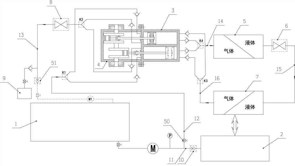
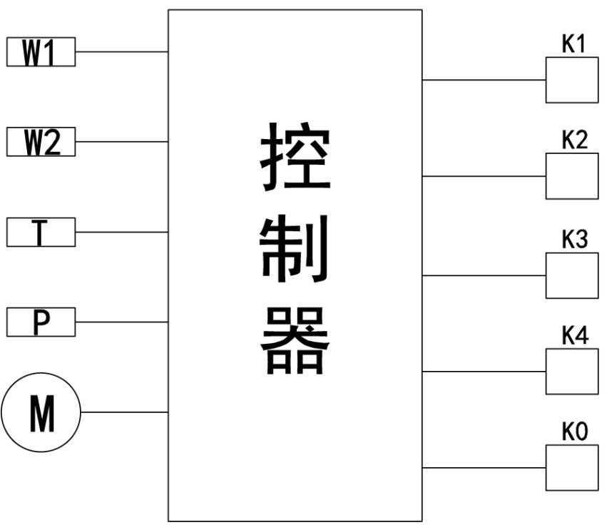
[0026] Embodiment 1: A gas cylinder inflation control device, which includes a gas tank 1 (compressed gas inflation equipment) and a gas cylinder 2 as a gas source for gas supply, and the device is suitable for the application of a variety of compressed liquefied gas inflation control, Such as compressed air, oxygen, liquefied petroleum gas, natural gas, inert gas or corrosive gas, etc., wherein, the output end of the gas tank 1 is pressurized by the gas pump (or compressor), and then connected to the gas tank through the gas connector 10 bottle 2. It also includes a cooling mechanism. The pressure supply main pipe 12 is drawn out from the inflation pipe 11 to perform work on the cooling mechanism. The evaporator 7 at the output end of the cooling mechanism is connected to the gas cylinder through a heat-conducting component, and is controlled by the controller according to the inflation progress in the gas cylinder 2. The power of the air pump increases until the cylinder is ...

Embodiment 2

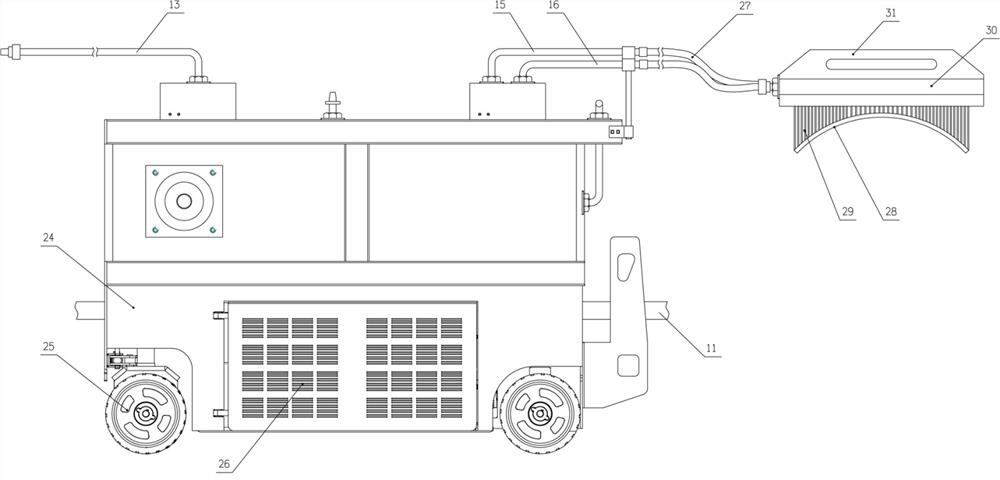
[0037] Embodiment 2: as Figure 5 As shown, on the basis of the improvement of the condenser in Embodiment 1, in this embodiment, a shaft tube 33 is connected to the rear side of the sealing box 30 through a fixing seat 32, and one end of the handle 34 is set on the shaft through a shaft sleeve 35. On the outside of the tube 33, a connector 36 is arranged at the end of the shaft tube, and a guide rod 39 is set on the other end of the handle through the sleeve 2 37. The front end of the guide rod is designed as an arc-shaped hook body 38 for clamping the gas cylinder. A rear seat and a handle 40 are arranged at the rear end of the guide rod, and a thrust spring is connected between the second axle sleeve and the rear seat.

Embodiment 3

[0038] Embodiment 3: A kind of gas tank inflation control device, such as Figure 6 As shown, the compressed gas from the compressed gas pipeline or the total storage tank 42 is introduced into the compressed gas transport vehicle-mounted gas tank through the inflation pipe, the air pump and the inflation joint 10, and the gas tank as described in Embodiment 1 is arranged near the vehicle-mounted gas tank. Cool down the power system. Such as Figure 6 As shown in , the dotted line part is the system arranged on the compressed gas transport vehicle. The detailed structure of the system is described in Implementation 1, and will not be described in detail. The system has three external joints: the inflation joint 10 and the pressurization joint 43 And return air joint 44. The inflation joint 10 is connected with the inflation pipe 11 , the booster joint 43 is connected with the booster main pipe 12 , and the air return joint 44 is connected with the return main pipe 13 .


PUM


Abstract

The invention discloses a gas cylinder inflation control device, which includes a gas tank and a gas cylinder as a gas source for supplying gas. After the gas tank output end is pressurized by an air pump, the gas cylinder is connected to the gas cylinder through an inflation joint, and also includes a cooling device. Mechanism, the pressure supply main pipe is drawn from the inflation pipe to do work on the cooling mechanism, the evaporator at the output end of the cooling mechanism is connected to the gas cylinder through a heat-conducting component, and the controller controls the power of the air pump to increase according to the inflation progress in the gas cylinder until the gas cylinder is full stop after. The invention can automatically increase the refrigeration power as the gas cylinder is heated up due to the increase of the inflation pressure, and the refrigeration system hardly participates in the cooling work at the initial stage of inflation, but can automatically perform cooling and cooling due to the temperature rise in the gas cylinder at the later stage of inflation. Automatically changes the cooling level as the cylinder temperature changes.

Description

technical field [0001] The invention belongs to the technical field of gas cylinder inflation control equipment, and in particular relates to a control technology applied to compressed gas inflation equipment for gas cylinder inflation. Background technique [0002] Gas cylinders refer to refillable gas under normal ambient temperature (-40-60°C), with a nominal working pressure of 1.0-30 MPa (gauge pressure), and a product of pressure and volume greater than or equal to 1.0 MPa·L. , mobile pressure vessels for liquefied gases and liquids with a standard boiling point equal to or lower than 60°C. Gas cylinders are widely used, whether in the field of production or in the field of life, gas cylinders are almost inseparable. As pressure equipment, its bearing medium is generally flammable, explosive, toxic, and highly corrosive. The use environment is more difficult than other pressure vessels due to its characteristics of movement, repeated filling, unfixed operators and cha...

Claims


Application Information

Patent Timeline
Patent Type & Authority Patents(China)
IPC IPC(8): F17C5/02F17D1/04F17D3/01
CPCF17C5/02F17D1/04F17D3/01F17C2227/0135F17C2265/032F17C2227/0337F17C2270/0178
Inventor 张平靳巍峰李媛媛刘娟刘晓丹王晨希田晓婕梁本栋李云慧
Owner 河南省标准化研究院
Learn More