An Aircraft Hydraulic Duct Seal Test Bench That Can Simulate Operating Conditions and Installation Errors
An installation error, aircraft hydraulic technology, applied in the field of aircraft hydraulic duct seal test bench, can solve problems such as the great influence of duct installation process parameters, and achieve the effect of simple and convenient adjustment process
- Summary
- Abstract
- Description
- Claims
- Application Information
AI Technical Summary
Problems solved by technology
Method used
Image
Examples
Embodiment 1
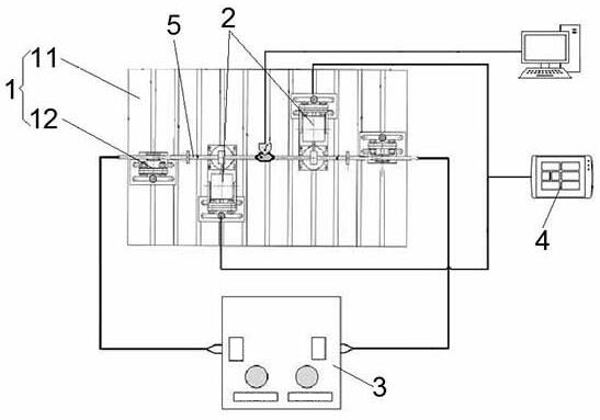
[0037] A sealing test bench for aircraft hydraulic conduit 5 that can simulate working conditions and installation errors in this embodiment, such as figure 1 As shown, an installation and adjustment test bench 1 for installing and adjusting the installation posture of the hydraulic conduit 5 is included, and at least one set of vibration excitation devices 2 for applying vibration to the hydraulic conduit 5 are slidably installed on the installation and adjustment test bench 1, so The installation and adjustment test bench 1 is also equipped with a signal acquisition device 4 for collecting vibration signals and stress changes of the hydraulic conduit 5; 3.
[0038] The installation and adjustment test bench 1 is used to install and fix hydraulic conduits 5 and conduit joints of various sizes and shapes, and to adjust the installation spacing, installation deviation, and installation deviation of the hydraulic conduits 5 to simulate the hydraulic conduits 5 in actual conditio...
Embodiment 2
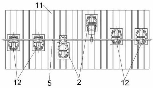
[0041] This embodiment is further optimized on the basis of Embodiment 1, such as figure 1 , image 3 , Figure 4 As shown, the installation and adjustment test bench 1 includes a bottom plate 11 and a conduit adjustment seat 12. A plurality of parallel chutes are linearly arranged on the bottom plate 11, and the conduit adjustment seats 12 are slidably installed in the chute on both sides of the bottom plate 11. .
[0042] The installation and adjustment test bench 1 includes at least one base plate 11, and a plurality of chutes parallel to the width direction of the base plate are linearly arranged on the base plate 11 along the length direction. The position of the conduit adjusting seat 12 in the length direction on the bottom plate 11 can be changed in different chute, and the conduit adjusting seat 12 can slide along the chute to change the position of the conduit adjusting seat 12 in the width direction on the bottom plate 11 . At the same time, the conduit adjusting...
Embodiment 3
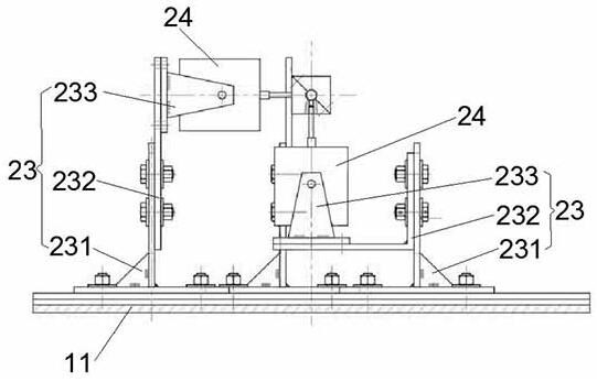
[0048] This embodiment is further optimized on the basis of the above-mentioned Embodiment 1 or 2, such as Figure 8 As shown, the excitation device 2 includes an excitation generator 21, an amplifier 22, an excitation mount 23, and a vibration exciter 24. The excitation mount 23 is slidably installed on the installation and adjustment test bench 1. A vibration exciter 24 is installed on the top of the vibration mounting base 23 along the horizontal or vertical direction, and the vibration exciter 24 receives the excitation signal sent by the vibration excitation generator 21 through the amplifier 22 .
[0049] The staff presets an excitation signal of a certain frequency and power through the excitation generator 21, and then the excitation signal is amplified by the amplifier 22 and then transmitted to the vibration exciter 24, and the vibration exciter 24 is installed in the installation adjustment through the excitation mounting seat 23. on the bottom plate 11 of the test ...
PUM
 Abstract
Description
Claims
Application Information
 - R&D
- Intellectual Property
- Life Sciences
- Materials
- Tech Scout
- Unparalleled Data Quality
- Higher Quality Content
- 60% Fewer Hallucinations
Browse by: Latest US Patents, China's latest patents, Technical Efficacy Thesaurus, Application Domain, Technology Topic, Popular Technical Reports.
© 2025 PatSnap. All rights reserved.Legal|Privacy policy|Modern Slavery Act Transparency Statement|Sitemap|About US| Contact US: help@patsnap.com


