
Raw material conveying equipment for building bridge

A technology for conveying equipment and raw materials, which is applied in the direction of freight vehicles, transportation and packaging, and load fixing, etc. It can solve problems such as poor stability of steel pipe reinforcement structures, easy sliding of tubular steel materials forward, and difficulty in taking and placing steel pipes. It achieves the effect of comprehensive protection action and high strength of blocking protection structure and high strength of protection structure

Active Publication Date: 2021-05-25
江苏中泰建发集团有限公司
View PDF15 Cites 0 Cited by
  • Summary
  • Abstract
  • Description
  • Claims
  • Application Information

AI Technical Summary

Problems solved by technology

[0002] The raw materials for building bridges mainly include the following: sand and gravel materials, steel, concrete, water and non-metallic profiles. Among them, the shape of the steel is mainly tubular. When the existing flatbed vehicles transport piles of tubular steel, there are the following: Two problems: first, the tubular steel is relatively easy to roll off the sides of the vehicle; second, after the vehicle brakes suddenly, the tubular steel is relatively easy to slide forward and pierce the cab. Once these two problems occur, it will be an extremely dangerous traffic accident , it is very easy to cause casualties
[0005] However, the steel pipe transport vehicle in this utility model patent has the problems of poor stability of the steel pipe reinforcement structure, and relatively large problems of difficulty in picking and placing the steel pipes.

Method used


Image

  • Raw material conveying equipment for building bridge
  • Raw material conveying equipment for building bridge
  • Raw material conveying equipment for building bridge

Examples


Embodiment

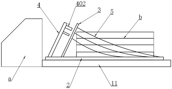
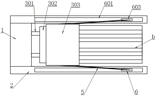
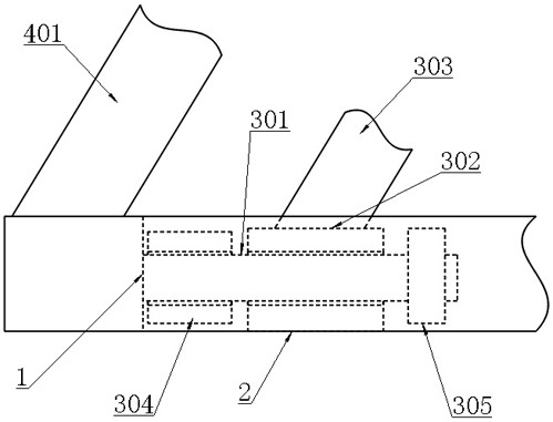
[0025] Example: as attached figure 1 , 2 , 3, 4, 5 and attached Image 6 As shown, a raw material conveying equipment for building a bridge includes a transport vehicle bottom plate 11, and also includes an intermediate plate 1 arranged on the upper surface of the transport vehicle bottom plate 11 and at a position close to the side of the cab a, respectively arranged on The two ends of the middle plate 1 and the two side plates 2 located on both sides of the pile of steel pipes b are arranged on the side of the middle plate 1 close to the steel pipe b and are used to prevent the vehicle from sliding forward when braking suddenly The movable inclined baffle unit 3 of the steel pipe is arranged on the upper surface of the middle plate 1 and is used to block and fix the fixed inclined baffle unit 4 of the movable inclined baffle unit 3, which is respectively arranged on the two side plates 2 and between the two sides of the movable inclined baffle unit 3 and are used to pull a...


PUM


Abstract

The invention belongs to the technical field of roads and bridges, and particularly relates to raw material conveying equipment for building a bridge. By arranging a middle plate, side plates, movable inclined baffle units, fixed inclined baffle units, inclined pull ropes and sliding plate units on the bottom plate of the transport vehicle, the conveying equipment has the advantages that the front end and the two sides have the limiting protection effect when steel pipe raw materials are transported, and steel pipes are convenient and rapid to load and unload. The steel pipe front end blocking protection structure is high in strength, the sliding steel pipe is not prone to colliding with a cab when a vehicle is braked suddenly, the inclined pull rope protection structures on the two sides of the steel pipe are high in strength, the steel pipe sliding from the side edge is not prone to falling on the ground when the vehicle is braked suddenly or turns, and pedestrian safety is not prone to being harmed; the inclined pull ropes can be retracted when the steel pipe is loaded or unloaded; the conveying equipment has the advantages that two-side space can be vacated for loading and unloading of steel pipes, the whole conveying equipment is high in structural strength, protection of the steel pipes is comprehensive and thorough, and overall transportation and use are efficient and safe.

Description

technical field [0001] The invention belongs to the technical field of roads and bridges, and in particular relates to a raw material conveying device for building bridges. Background technique [0002] The raw materials for building bridges mainly include the following: sand and gravel materials, steel, concrete, water and non-metallic profiles. Among them, the shape of the steel is mainly tubular. When the existing flatbed vehicles transport piles of tubular steel, there are the following: Two problems: first, the tubular steel is relatively easy to roll off the sides of the vehicle; second, after the vehicle brakes suddenly, the tubular steel is relatively easy to slide forward and pierce the cab. Once these two problems occur, it will be an extremely dangerous traffic accident , is very likely to cause casualties. [0003] Therefore, there is an urgent need for a transport vehicle with a tubular steel protection structure on the market to ensure that piles of tubular st...

Claims


Application Information

Patent Timeline
Patent Type & Authority Applications(China)
IPC IPC(8): B60P7/12B60P7/16
CPCB60P7/12B60P7/16
Inventor 李全刘桂香柏平夏加波常帅帅孙振宇
Owner 江苏中泰建发集团有限公司
Learn More