
Liquid ejecting head and liquid ejecting system

A liquid ejection head, liquid technology, applied in the direction of inking device, printing, etc.

Pending Publication Date: 2021-06-04
SEIKO EPSON CORP
View PDF1 Cites 0 Cited by
  • Summary
  • Abstract
  • Description
  • Claims
  • Application Information

AI Technical Summary

Problems solved by technology

In the conventional liquid jet head, there is room for further improvement from the viewpoint of efficient arrangement of a plurality of flow channels.

Method used


Image

  • Liquid ejecting head and liquid ejecting system
  • Liquid ejecting head and liquid ejecting system
  • Liquid ejecting head and liquid ejecting system

Examples


Embodiment Construction

[0027] A: The first embodiment

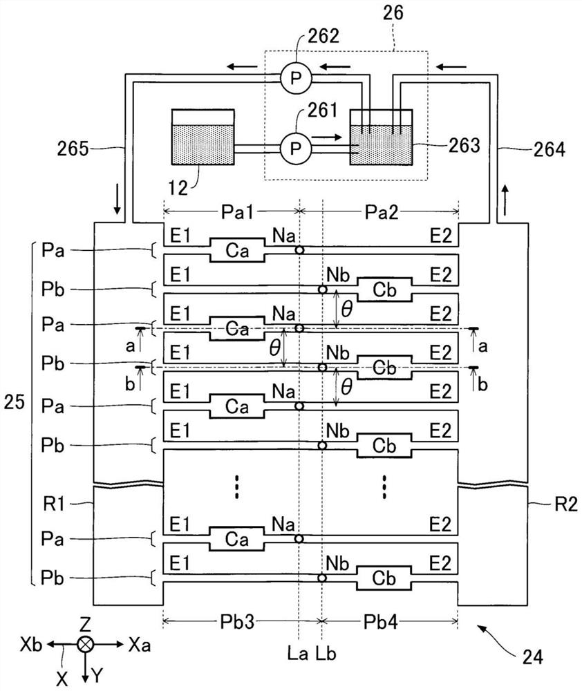
[0028] like figure 1 As illustrated, in the following description, an X-axis, a Y-axis, and a Z-axis that are perpendicular to each other are assumed. One direction along the X-axis when observed at an arbitrary point is denoted as an Xa direction, and the opposite direction to the Xa direction is denoted as an Xb direction. The X-Y plane including the X-axis and the Y-axis corresponds to a horizontal plane. The Z axis is an axis along the vertical direction, and the positive direction of the Z axis corresponds to the downward direction in the vertical direction.

[0029] figure 1 It is a configuration diagram illustrating an exemplary configuration of a part of the liquid ejection system 100 according to the first embodiment. The liquid ejection system 100 of the first embodiment is an inkjet type printing device that ejects droplets of ink, which is an example of liquid, onto a medium 11 . The medium 11 is, for example, printing paper. ...


PUM


Abstract

The invention provides a liquid ejecting head and a liquid ejecting system in which a plurality of flow paths are efficiently arranged in the liquid ejecting head. The liquid ejecting head includes a separate flow path column in which a plurality of separate flow paths communicating with nozzles that eject liquid in a direction of a first axis are arranged along a second axis orthogonal to the first axis, and a first common liquid chamber communicating with the plurality of separate flow paths. Each of the plurality of individual flow channels includes a pressure chamber for storing a liquid.

Description

technical field [0001] The present invention relates to a liquid ejection head and a liquid ejection system. Background technique [0002] Conventionally, there have been proposed liquid ejection heads that eject liquid such as ink from a plurality of nozzles, for example. For example, Patent Document 1 discloses a liquid ejection head that changes the pressure of liquid in a pressure chamber by using a piezoelectric element to eject liquid from a nozzle communicating with the pressure chamber. [0003] In recent liquid jet heads, it is required to arrange a plurality of nozzles at a high density. On the other hand, in order to arrange a plurality of nozzles at a high density, it is necessary to efficiently arrange flow paths including pressure chambers. In the conventional liquid jet head, there is room for further improvement from the viewpoint of efficient arrangement of a plurality of channels. [0004] Patent Document 1: Japanese Patent Laid-Open No. 2013-184372 Co...

Claims


Application Information

Patent Timeline
IPC IPC(8): B41J2/01B41J2/14
CPCB41J2/01B41J2/14201B41J2/14233B41J2002/14241B41J2002/14419B41J2002/14411B41J2202/11B41J2002/14475B41J2/18B41J2002/14306
Inventor 福泽祐马玉井捷太郎长沼阳一宫岸晓良内田和见
Owner SEIKO EPSON CORP
Learn More