
Camera assembly and electronic equipment

A technology for photographing components and electronic equipment, applied in the field of communication, can solve problems such as reduced portability of equipment, and achieve the effects of improved portability, convenient use, and adjustable shading amount

Pending Publication Date: 2021-06-25
VIVO MOBILE COMM CO LTD
View PDF8 Cites 1 Cited by
  • Summary
  • Abstract
  • Description
  • Claims
  • Application Information

AI Technical Summary

Problems solved by technology

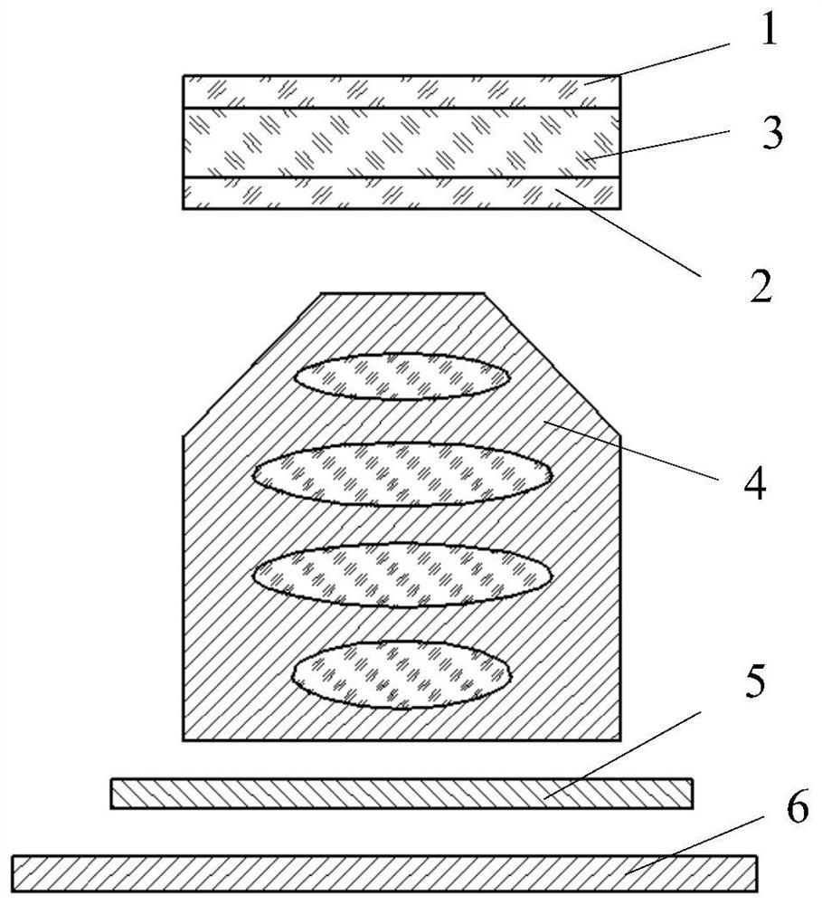
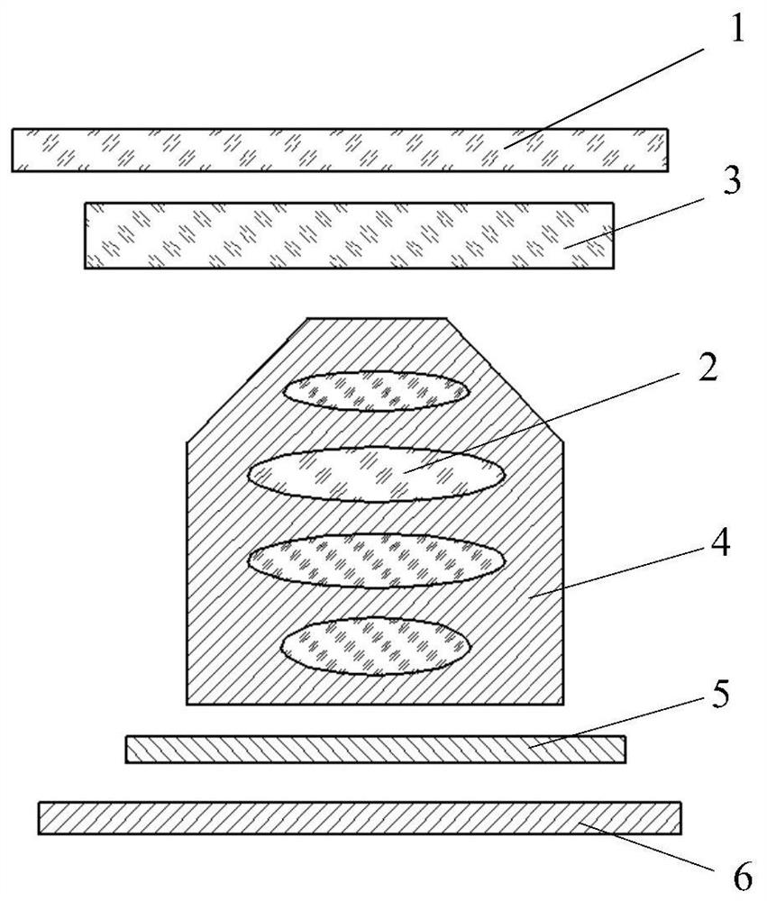
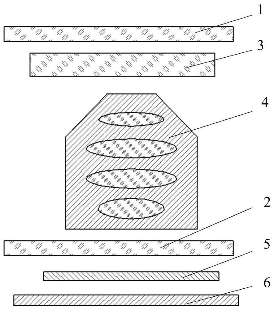
[0004] The purpose of the embodiment of the present application is to provide a camera assembly and electronic equipment, which can solve the problem of reduced portability of the equipment due to the need to add an external light reduction mirror when the camera assembly realizes long exposure during the day

Method used


Image

  • Camera assembly and electronic equipment
  • Camera assembly and electronic equipment
  • Camera assembly and electronic equipment

Examples


Embodiment Construction

[0023] The following will clearly describe the technical solutions in the embodiments of the present application with reference to the drawings in the embodiments of the present application. Obviously, the described embodiments are part of the embodiments of the present application, but not all of them. All other embodiments obtained by persons of ordinary skill in the art based on the embodiments in this application belong to the protection scope of this application.

[0024] The terms "first", "second" and the like in the specification and claims of the present application are used to distinguish similar objects, and are not used to describe a specific sequence or sequence. It should be understood that the terms so used are interchangeable under appropriate circumstances such that the embodiments of the application can be practiced in sequences other than those illustrated or described herein, and that references to "first," "second," etc. distinguish Objects are generally o...


PUM


Abstract

The invention discloses a camera assembly and electronic equipment and belongs to the technical field of communication. The camera assembly comprises a first linear polarization piece, a second linear polarization piece and a magnetic control optical rotation device which are all located in a light path of the shooting assembly, the second linear polarization part is located outside or inside the lens; the magnetic control optical rotation device is located between the first linear polarization piece and the second linear polarization piece, the first linear polarization piece and the second linear polarization piece are both used for changing the polarization direction of light, and the light polarization rotation angle of the magnetic control optical rotation device changes along with the change of the magnitude of the energizing current in the magnetic control optical rotation device. The camera assembly is advantaged in that the shading amount of the shooting assembly can be adjusted directly by means of the built-in first linear polarization piece, the built-in second linear polarization piece and the built-in magnetic control optical rotation device, long exposure can be carried out in the daytime, meanwhile, a light reducing mirror does not need to be additionally arranged outside the shooting assembly, and portability of the shooting assembly is improved.

Description

technical field [0001] The present application belongs to the technical field of communication, and in particular relates to a camera assembly and electronic equipment. Background technique [0002] With the continuous development of electronic equipment, the performance of electronic equipment is becoming more and more powerful, especially the progress of electronic equipment in shooting technology is particularly obvious. In order for the electronic device to be used to take photos in dynamic environments such as flowing clouds in the sky and flowing water on the ground, the electronic device usually needs to have a "long exposure" shooting function. [0003] At present, in order to allow long exposures during the day, it is usually necessary to add an external light reduction filter to the camera to reduce the amount of light entering the lens. However, adding an external light reduction mirror to the camera of the electronic device will reduce the portability of the ele...

Claims


Application Information

Patent Timeline
Patent Type & Authority Applications(China)
IPC IPC(8): G03B7/18G03B30/00
CPCG03B7/18
Inventor 陈宇灏
Owner VIVO MOBILE COMM CO LTD
Learn More