Supercharge Your Innovation With Domain-Expert AI Agents!

Probe

A technology of probes and flanges, which is applied in the field of connector probes, and can solve problems such as easy reduction of characteristic inspection accuracy, misalignment of terminals and probes, etc.

Pending Publication Date: 2021-06-25
MURATA MFG CO LTD
View PDF1 Cites 0 Cited by
  • Summary
  • Abstract
  • Description
  • Claims
  • Application Information

AI Technical Summary

Problems solved by technology

Like the probe of Patent Document 1, when a plurality of probes are brought into contact with a plurality of terminals at the same time, misalignment between the terminals and the probes tends to occur, and the accuracy of characteristic inspection tends to decrease.

Method used


Image

  • Probe
  • Probe
  • Probe

Examples


Embodiment approach 1

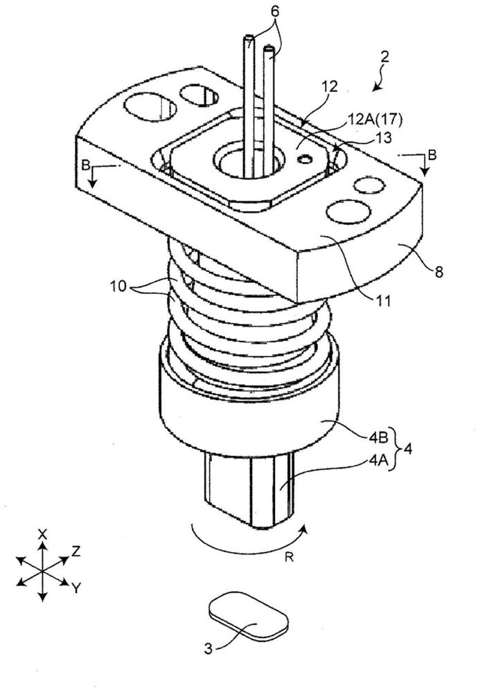
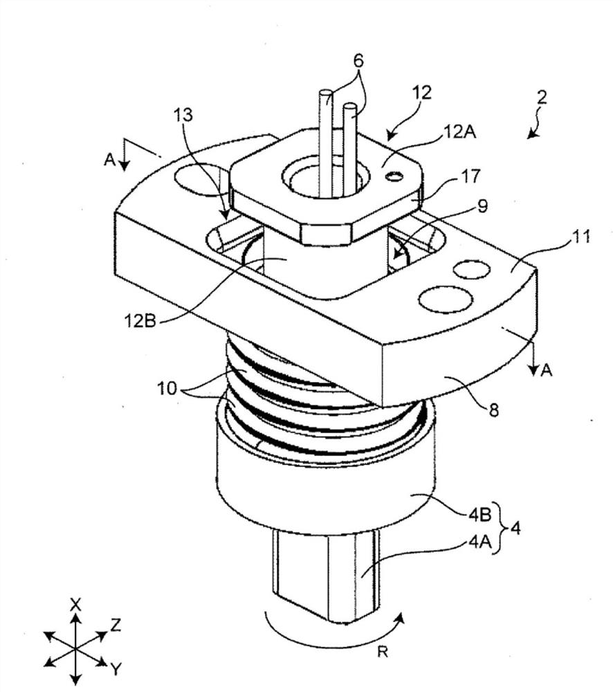
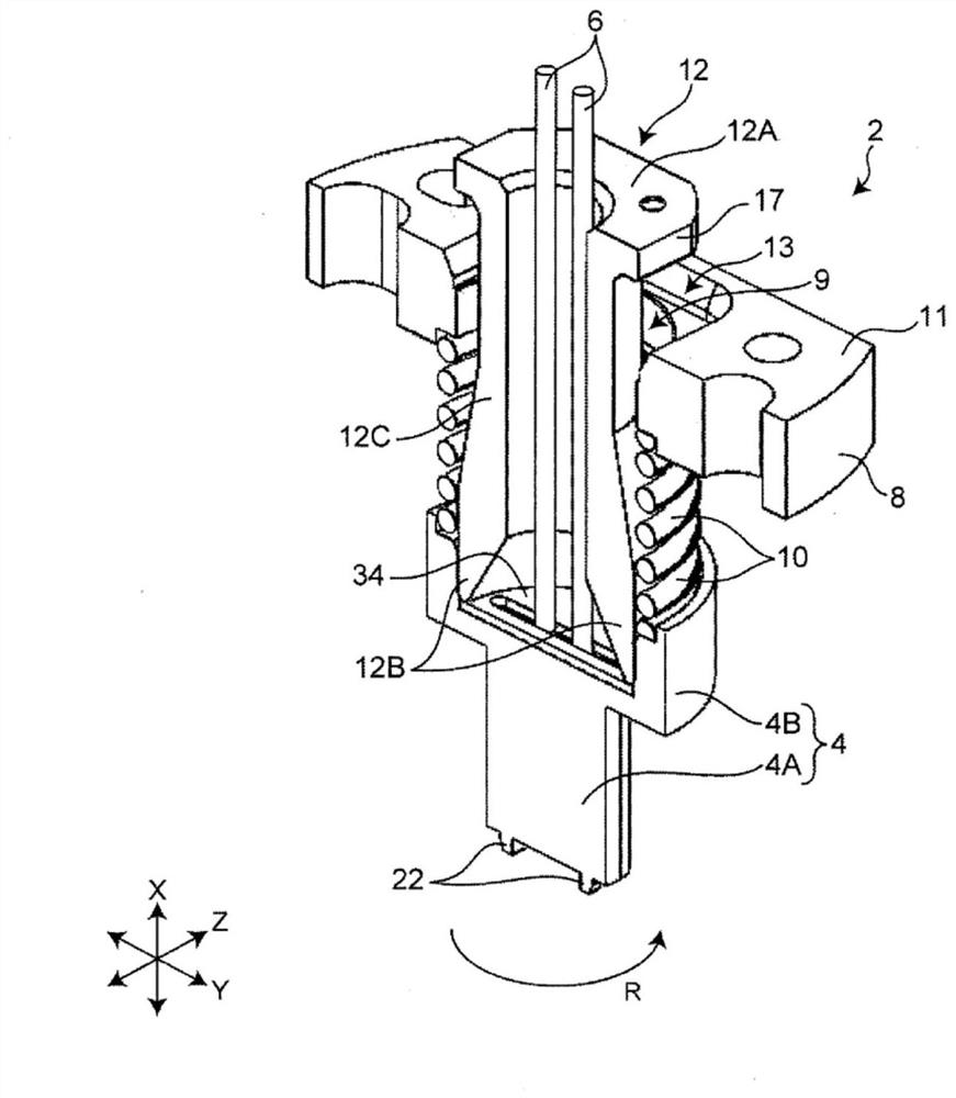
[0049] Figure 1-Figure 5 It is a figure which shows the schematic structure of the probe 2 of Embodiment 1. figure 1 , figure 2 is a schematic perspective view showing different states of the probe 2 . image 3 yes means figure 2 A cross-sectional view of the A-A section in, Figure 4 yes means figure 1 Sectional view of the B-B section in . Figure 5 It is an exploded perspective view of probe 2. exist Figure 1-Figure 5 , let the vertical direction be the X direction, and let the mutually orthogonal horizontal directions be the Y direction and the Z direction.

[0050] The probe 2 is an inspection tool for inspecting the characteristics of the connector 3 . The connector 3 of Embodiment 1 is a multi-pole connector having a plurality of terminals. The probe 2 has a plunger 4, a coaxial cable 6, a flange 8, a spring 10, a housing 12, a probe 16 ( Figure 4 , Figure 5 ) and plate 34.

[0051] The plunger 4 is a positioning member for fitting the connector 3 and ...

Embodiment approach 2

[0097] use Figure 9-Figure 16B The probe 40 according to Embodiment 2 of the present invention will be described. In addition, in Embodiment 2, differences from Embodiment 1 will be mainly described.

[0098] Figure 9-Figure 13 It is a figure which shows the schematic structure of the probe 40 of Embodiment 2. Figure 9 , Figure 11 is a schematic perspective view showing different states of the probe 2 . Figure 10 yes Figure 9 E-E section view in, Figure 12 yes Figure 11 Sectional view F-F in . Figure 13 It is an exploded perspective view of the probe 40 . exist Figure 9-Figure 13 In the same manner, the vertical direction is set as the X direction, and the horizontal directions perpendicular to each other are set as the Y direction and the Z direction.

[0099] The probe 40 of the second embodiment includes the plunger 4 , the coaxial cable 6 , and the spring 10 having the same structures as those of the first embodiment, and includes a flange 42 and a hous...


PUM


Abstract

This probe for inspecting characteristics of a connector is provided with a plunger, a coaxial cable, a flange, and a housing. An end part of one side of the housing has an expanded-diameter part where the diameter is expanded in the horizontal direction from a main body. An upper surface of the flange has formed thereon a concavity for enlarging a through hole in the horizontal direction so as to receive the expanded-diameter part of the housing. The expanded-diameter part has a side wall partially in contact with or facing an inside surface of the flange where the concavity is formed, and a bottom wall abutting against the upper surface of the flange where the concavity is formed. The expanded-diameter part has a connecting surface for connecting the side wall and the bottom wall, and the connecting surface is an inclined surface inclined inward toward the bottom wall from the side wall; or, the inside surface of the flange where the concavity is formed has a first surface that is inclined obliquely downward, and a vertical surface that extends downward from the first surface and is connected to the upper surface of the flange is a second surface.

Description

technical field [0001] The present invention relates to a probe for a connector. Background technique [0002] Conventionally, a probe for performing characteristic inspection of a connector as an object to be inspected has been disclosed (for example, refer to Patent Document 1). [0003] The probe of Patent Document 1 is particularly an apparatus for performing characteristic inspection of a multi-pole connector provided with a plurality of terminals for allowing a plurality of signals to flow. The probe of Patent Document 1 includes a plurality of probes capable of simultaneously contacting a plurality of terminals of a multipolar connector. [0004] Patent Document 1: Japanese International Publication No. 2016 / 072193 [0005] With regard to probes for connectors, it is required to improve the accuracy of characteristic inspection. Like the probe of Patent Document 1, when a plurality of probes are brought into contact with a plurality of terminals at the same time, m...

Claims


Application Information

Patent Timeline
Patent Type & Authority Applications(China)
IPC IPC(8): G01R1/067G01R1/073H01R13/631H01R43/00
CPCG01R1/06722G01R1/06716G01R1/04G01R1/0408G01R1/06738G01R31/66H01R43/002H01R13/6315G01R1/06733H01R13/631H01R43/00H01R13/629
Inventor 末政肇剑崎真一
Owner MURATA MFG CO LTD
Features
  • R&D
  • Intellectual Property
  • Life Sciences
  • Materials
  • Tech Scout
  • Unparalleled Data Quality
  • Higher Quality Content
  • 60% Fewer Hallucinations
Learn More