Cold heading die structure capable of adjusting direction of forming cavity

A forming cavity and cold heading technology, which is applied in the direction of manufacturing tools, forging/pressing/hammer devices, forging/pressing/hammering machinery, etc., can solve the problem of large randomness, inability to achieve fine-tuning, and inability to effectively solve product shape and position tolerances, etc. problem, to achieve the effect of easy operation and simple operation

Pending Publication Date: 2021-07-09
ZHOUSHAN 7412 FACTORY
View PDF0 Cites 0 Cited by
  • Summary
  • Abstract
  • Description
  • Claims
  • Application Information

AI Technical Summary

Problems solved by technology

[0002] For non-revolving cold heading parts, the original cold heading process has been unable to effectively solve the problem of shape and position tolerance of the product
In the existing cold heading forming process, the cold heading mold can only be rotated by the feeling of the cold heading master. After the cold heading mold is rotated, the clamping screw of the equipment is fixed to debug the product. The operation is random and cannot be realized only by manual feeling. Fine-tuning, it is difficult to debug the shape and position tolerance size that meets the product requirements, so the cold heading structure used in the existing process still needs to be improved

Method used


Image

  • Cold heading die structure capable of adjusting direction of forming cavity
  • Cold heading die structure capable of adjusting direction of forming cavity
  • Cold heading die structure capable of adjusting direction of forming cavity

Examples


Embodiment Construction

[0024] The present invention will be further described in detail below in conjunction with the accompanying drawings and embodiments.

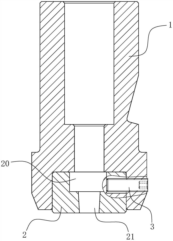
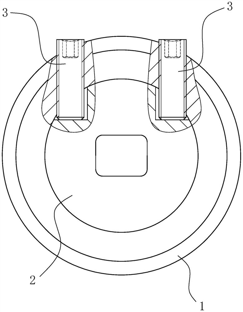
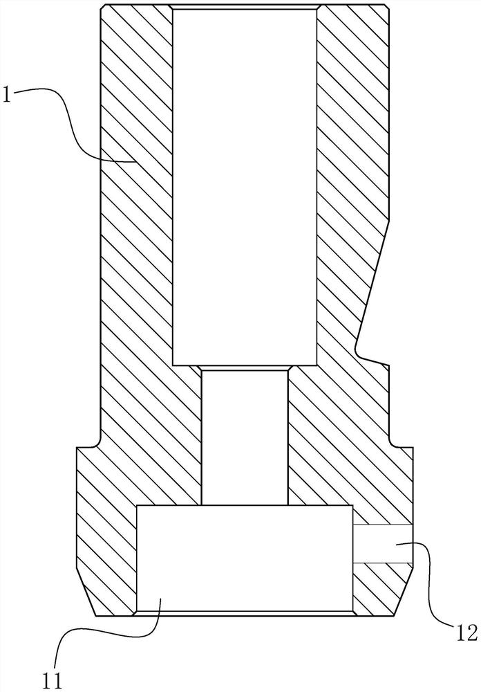
[0025] Such as Figure 1 to Figure 6 As shown, the cold heading die structure capable of adjusting the direction of the forming cavity in this embodiment includes an outer mold shell 1 and an inner mold body 2, the inner mold body 2 is detachably arranged at the bottom of the outer mold shell 1, and the bottom surface of the inner mold body 2 A molding cavity capable of cold heading parts is provided on the top, and an installation cavity 11 capable of installing the inner membrane body 2 is arranged at the bottom of the outer mold shell 1. Threaded holes 12 are distributed on the side wall at the bottom of the outer mold shell 1, and corresponding adjusting screws 3 are screwed in the threaded holes 12. Touching together, when the tail ends of the adjusting screws 3 are respectively screwed to change the length of the top of the correspondin...


PUM


Abstract

A cold heading die structure capable of adjusting the direction of a forming cavity comprises an outer die shell and an inner die body, the inner die body is detachably arranged at the bottom of the outer die shell, the forming cavity is formed in the bottom face of the inner die body, an installation cavity is formed in the bottom of the outer die shell, the inner die body can be detachably connected into the installation cavity, threaded holes are distributed in the side wall, corresponding to the installation cavity, of the bottom of the outer die shell, corresponding adjusting screws are connected into the threaded holes in a threaded mode, the top ends of the adjusting screws stretch into the installation cavity and abut against the outer wall of the inner die body, and when the tail ends of the adjusting screws are screwed to change the length, stretching into the installation cavity, of the top ends of the corresponding adjusting screws, the position of the inner die body in the installation cavity is changed, so that the direction of the forming cavity is changed. The cold heading die structure capable of adjusting the direction of the forming cavity has the advantages that the requirement of form and location tolerance of a product is met by continuously and finely adjusting the length, extending into the installation cavity, of the adjusting screws in the debugging process, fine adjustment of the direction of the forming cavity is realized, and the cold heading die structure is simple and easy to operate.

Description

technical field [0001] The invention relates to the technical field of mold making, in particular to a cold heading mold structure capable of adjusting the position of a forming cavity. Background technique [0002] For non-revolving cold heading parts, the original cold heading process has been unable to effectively solve the problem of shape and position tolerance of the product. In the existing cold heading forming process, the cold heading mold can only be rotated by the feeling of the cold heading master. After the cold heading mold is rotated, the clamping screw of the equipment is fixed to debug the product. The operation is random and cannot be realized only by manual feeling. Fine-tuning, it is difficult to debug the shape and position tolerance size that meets the product requirements, so the cold heading structure used in the existing process still needs to be improved. Contents of the invention [0003] The technical problem to be solved by the present inventi...

Claims


Application Information

Patent Timeline
IPC IPC(8): B21J13/02
CPCB21J13/02
Inventor 张理峰胡冰磊赵慈波
Owner ZHOUSHAN 7412 FACTORY
Why Eureka
Try Eureka