
Pneumatic finger

A pneumatic finger and air chamber technology, applied in the field of medical equipment, can solve the problem that prosthetic fingers cannot achieve abduction and adduction

Active Publication Date: 2021-07-09
BEIHANG UNIV
View PDF6 Cites 0 Cited by
  • Summary
  • Abstract
  • Description
  • Claims
  • Application Information

AI Technical Summary

Problems solved by technology

[0005] The invention provides a pneumatic finger, which is used to solve the problem that prosthetic fingers cannot achieve abduction and adduction in the prior art

Method used


Image

  • Pneumatic finger
  • Pneumatic finger
  • Pneumatic finger

Examples


Embodiment Construction

[0034] In order to make the purpose, technical solutions and advantages of the present invention clearer, the technical solutions in the present invention will be clearly and completely described below in conjunction with the accompanying drawings in the present invention. Obviously, the described embodiments are part of the embodiments of the present invention , but not all examples. Based on the embodiments of the present invention, all other embodiments obtained by persons of ordinary skill in the art without creative efforts fall within the protection scope of the present invention.

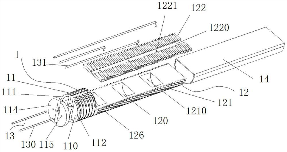
[0035] Combine below Figure 1-Figure 7 A pneumatic finger provided by the present invention is described.

[0036] Such as figure 1 As shown, the pneumatic finger 1 provided in this embodiment includes: a first section 11, a first air chamber 110 and an air supply device 13; The first area 111 and the second area 112; the first area 111 and the second area 112 are located on both sides of...


PUM


Abstract

The invention provides a pneumatic finger. The pneumatic finger comprises a first section, a plurality of first air chambers and an air supply device. The first air chambers are respectively arranged in a first area and a second area in the first section. The first area and the second area are located on the two sides of the axis direction of the first section. The air supply device respectively communicates with the first air chambers. Under the condition that the air pressure of the first air chambers in the first area is greater than that of the first air chambers in the second area, the first section is bent towards one side of the second area. Under the condition that the air pressure of the first air chambers in the first area is smaller than that of the first air chambers in the second area, the first section is bent towards one side of the first area. The first section of the pneumatic finger is bent towards one side of the first area or one side of the second area by changing the air pressure relation of the first air chambers in the first area and the second area, so that the extension and folding actions of the human finger are simulated.

Description

technical field [0001] The invention relates to the technical field of medical instruments, in particular to a pneumatic finger. Background technique [0002] Prosthetic limbs, also known as "prosthetic limbs", are artificial limbs used by amputees to replace part of the missing limb functions, allowing amputees to recover a certain degree of self-care and work ability. [0003] In existing prosthetic hand fingers, each knuckle is connected by a hinge, and each knuckle is driven to rotate around the hinge by a driving device. When the bending action is to be realized, the driving device drives each knuckle of the finger to rotate to the inside of the finger around the hinge. [0004] Existing prosthetic hands and fingers adopt hinged joints, which require many driving devices and complex structures. At the same time, existing prosthetic hands and fingers can only be bent or extended in one plane. In the vertical plane, the abduction and adduction movements of human fingers...

Claims


Application Information

Patent Timeline
Patent Type & Authority Applications(China)
IPC IPC(8): B25J15/00
CPCB25J15/0023
Inventor 王豫闫亚东张佳楠官明俊
Owner BEIHANG UNIV
Learn More