Device and method for testing dynamic friction coefficient of annular surface under dynamic impact

A technology of dynamic friction coefficient and testing device, which is applied in the field of measurement and detection, can solve the problems of inability to test the dynamic friction coefficient of the ring surface and low test accuracy, and achieve the effects of simple structure, simple and intuitive results, and convenient layout and use

Active Publication Date: 2022-03-01
NAT UNIV OF DEFENSE TECH
View PDF2 Cites 0 Cited by
  • Summary
  • Abstract
  • Description
  • Claims
  • Application Information

AI Technical Summary

Problems solved by technology

[0008] The technical problem to be solved by the present invention is to provide a test device and method for the friction coefficient between friction pairs under dynamic impact based on dynamic force sensor force measurement. The current test device and method can only test the maximum static friction coefficient, or test Low precision, unable to test the dynamic friction coefficient of the ring surface under dynamic impact, it can be used to test the friction coefficient of different friction pairs under different pressures and different impact speeds, and provide a new reference option for the test of friction coefficient under dynamic impact

Method used


Image

  • Device and method for testing dynamic friction coefficient of annular surface under dynamic impact
  • Device and method for testing dynamic friction coefficient of annular surface under dynamic impact
  • Device and method for testing dynamic friction coefficient of annular surface under dynamic impact

Examples


Embodiment Construction

[0044] The present invention will be described in detail below to facilitate the understanding of the present invention, and will be described in connection with the accompanying drawings and specific embodiments.

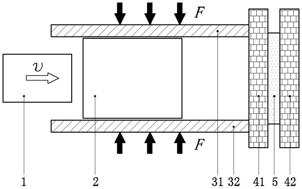
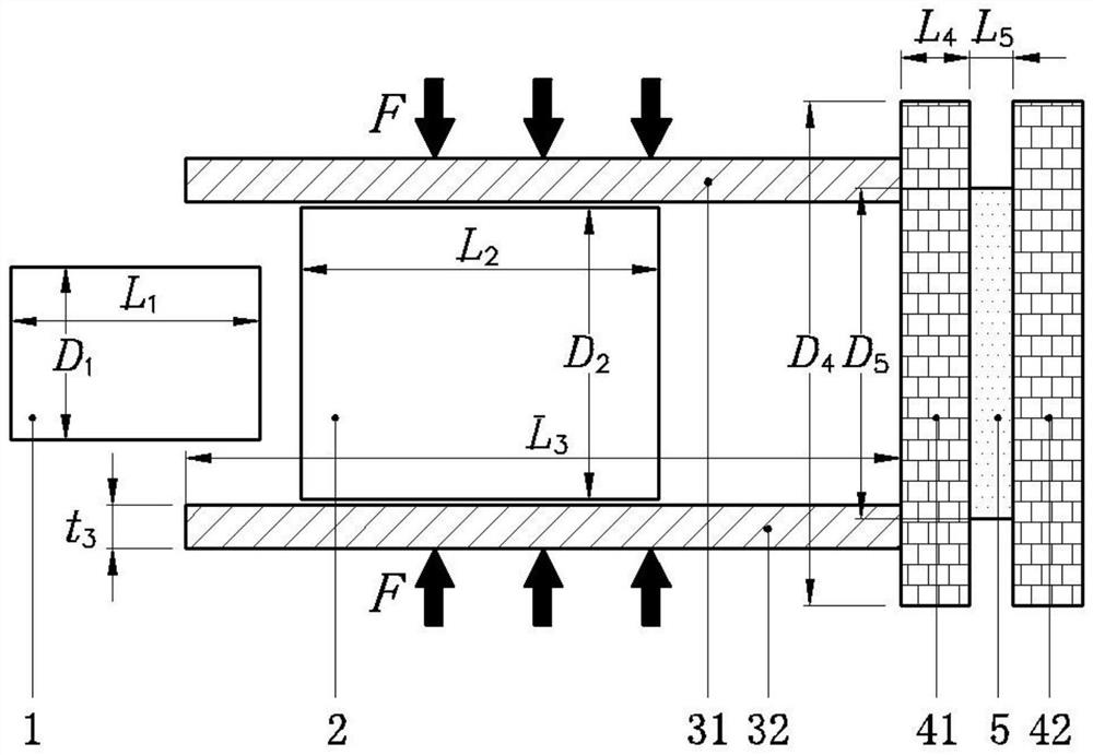
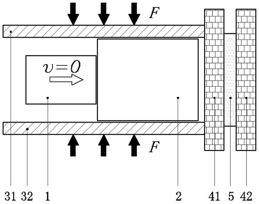
[0045] figure 1 The overall structure of the test device of the present invention is shown. Such as figure 1 As shown, the test apparatus of the present invention is made of a bell rod 1, and the first friction pair 2, two second friction pair (order is the upper second friction sub 31, the lower second friction pair 32), and two pieces (order to The left plate 41, the right plate 42), the dynamic force sensor 5. The left plate 41, the right plate 42 is in the same end of the test device. Definition The first end of the present invention is right end, defining one end of the present invention away from the right plate 42 as the left. The first friction pair 2 is located between the upper second friction sub 31, and the lower second friction sub 32 (when the first fric...


PUM

PropertyMeasurementUnit
diameteraaaaaaaaaa
yield strengthaaaaaaaaaa
densityaaaaaaaaaa

Abstract

The invention discloses a test device and method for dynamic friction coefficient of an annular surface under dynamic impact, aiming at obtaining accurate friction coefficient. The device of the present invention is composed of a striking rod, a first friction pair, an upper second friction pair, a lower second friction pair, a left support plate, a right support plate, and a dynamic force sensor. The three friction pairs left support plate, right support plate, dynamic The force sensor is mounted coaxially. The test method is to hit the left end face of the first friction pair with the impact rod, and the first friction pair, the upper second friction pair, and the lower second friction pair generate relative motion to generate friction force; the friction force is transmitted to the left support plate, and then the dynamic force The sensor converts it into a voltage signal and measures it, and combines the pressure on the upper second friction pair and the lower second friction pair to calculate the friction coefficient. The device of the invention has the advantages of simple structure, convenient layout, reusability, simple test method and high accuracy, and solves the technical problem that it is difficult to quantitatively test the friction coefficient of the annular surface under dynamic impact.

Description

Technical field [0001] The present invention belongs to the field of measurement detection, and more particularly to a device and method for dynamically impacting the annular surface surface dynamic coefficient test, and is a device and method for testing the dynamic impact load on the dynamic impact loading. Background technique [0002] In the contact behavior, there must always be relatively moving between objects, so it is inevitable with friction behavior. Friction is one of the important behaviors in contact, and friction is one of the important external forces in contact, which has remarkably impacts the contact process. Tribology is a system science, friction wear phenomenon is very complicated, a lot of influencing factors, such as the contact area of ​​friction, the humidity, temperature, size of the test, the size of the sliding speed, and the loading time. The friction is used as an outer load, which not only affects the size and energy dissipation of the object, but ...

Claims


Application Information

Patent Timeline
Patent Type & Authority Patents(China)
IPC IPC(8): G01N19/02
CPCG01N19/02
Inventor 林玉亮祁子真张玉武陈荣梁民族彭永李翔宇卢芳云
Owner NAT UNIV OF DEFENSE TECH
Why Eureka
Try Eureka