Inner chamfer machining robot for cylindrical parts

A robot and chamfering technology, applied in metal processing machinery parts, metal processing, metal processing equipment, etc., can solve problems such as poor processing accuracy, poor quality, and low efficiency

Active Publication Date: 2021-08-06
BINZHOU UNIV
View PDF10 Cites 3 Cited by
  • Summary
  • Abstract
  • Description
  • Claims
  • Application Information

AI Technical Summary

Problems solved by technology

Extremely low efficiency, poor machining accuracy, poor reliability, surface burrs, and poor quality

Method used


Image

  • Inner chamfer machining robot for cylindrical parts
  • Inner chamfer machining robot for cylindrical parts
  • Inner chamfer machining robot for cylindrical parts

Examples


Embodiment Construction

[0054] The following description serves to disclose the present invention to enable those skilled in the art to carry out the present invention. The preferred embodiments described below are only examples, and those skilled in the art can devise other obvious variations.

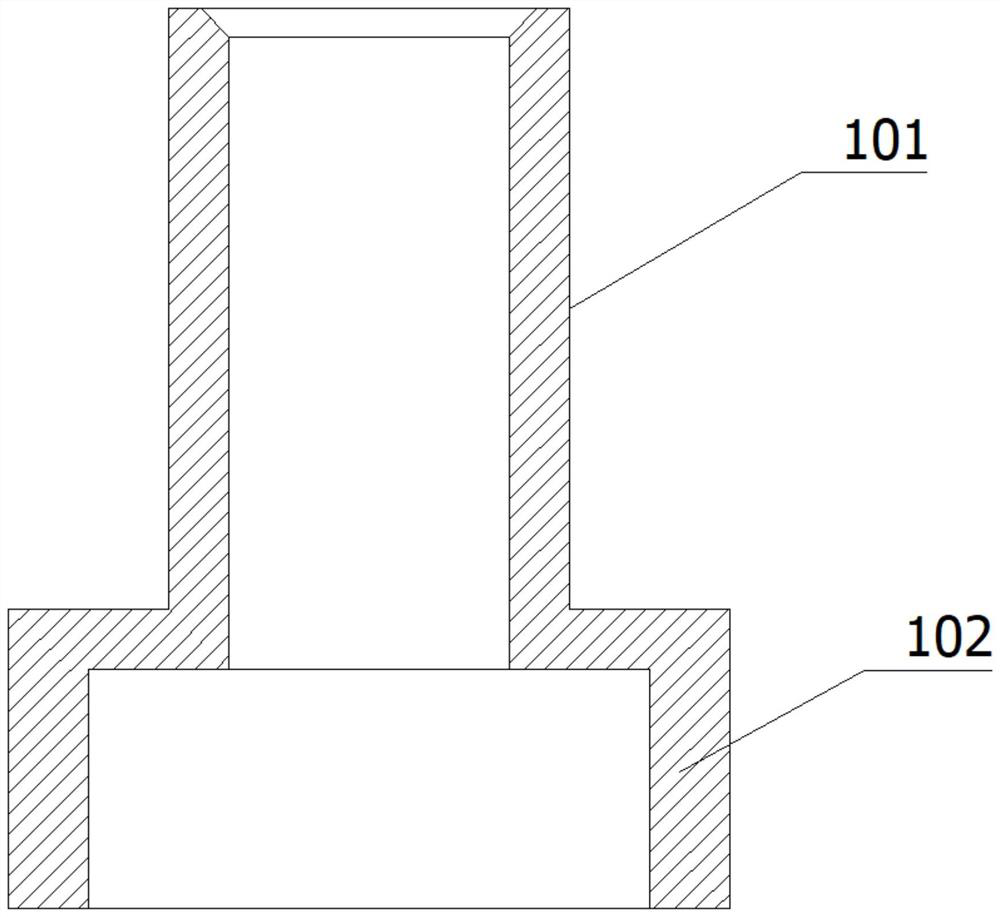
[0055] Such as figure 1Said, the cylindrical part includes a first cylinder 101 and a second cylinder 102, the first cylinder 101 and the second cylinder 102 are coaxially arranged, and one end of the second cylinder 102 is connected to the first cylinder 101 is connected at one end, and the outer diameter of the second cylindrical body 102 is larger than that of the first cylindrical body 101 .

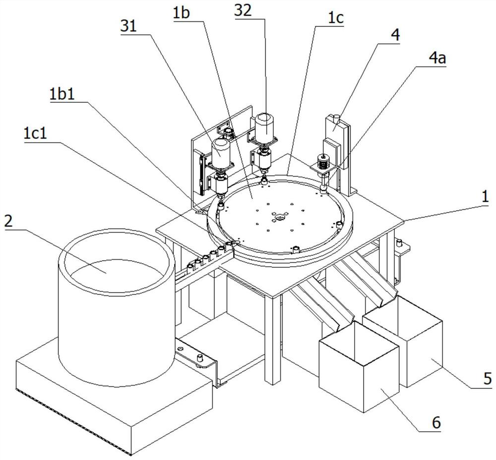
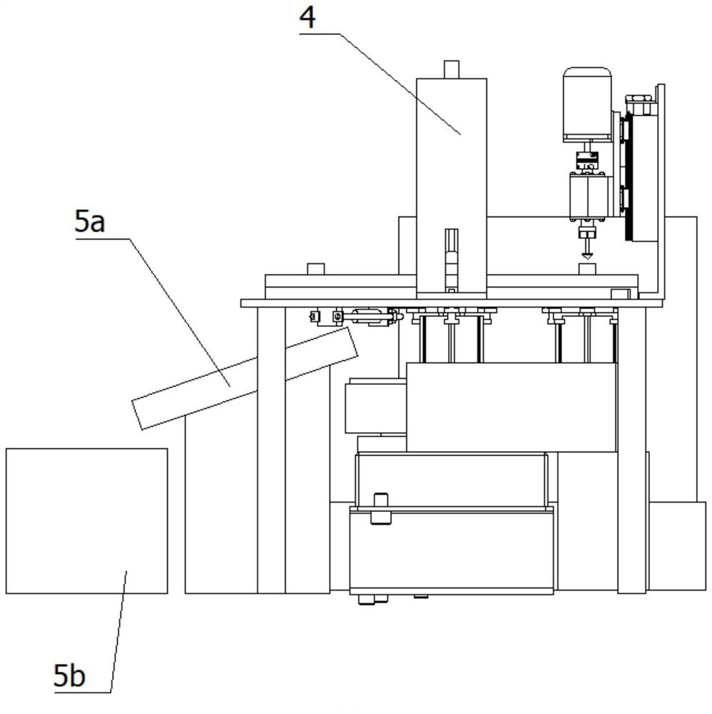
[0056] refer to Figure 2-11 As shown, a processing robot for internal chamfering of cylindrical parts includes a horizontally placed mounting plate 1, a rotating disk 1b that is rotatable along the vertical axis and located directly above the mounting plate 1, and a loading station The feeding assembly 2 for lo...


PUM


Abstract

The invention provides an inner chamfer machining robot for cylindrical parts. The inner chamfer machining robot for the cylindrical parts comprises a mounting plate, a rotating disc, a feeding assembly, a first chamfering assembly, a second chamfering assembly, a detection assembly, a first discharging assembly and a second discharging assembly; the mounting plate is horizontally arranged; the rotating disc can rotate along a vertical axis and is positioned right above the mounting plate; the feeding assembly is located on a feeding station and used for carrying out feeding on the cylindrical parts; the first chamfering assembly and the second chamfering assembly are located at a first chamfering station and a second chamfering station respectively and both supported on the mounting plate; the detection assembly is located at a detection station, is supported on the mounting plate and is used for carrying out detection on the chamfered cylindrical parts so as to judge whether chamfers are qualified or not; and the first discharging assembly and the second discharging assembly are located at a first discharging station and a second discharging station respectively and used for carrying out discharging on the cylindrical parts with qualified chamfers and the cylindrical parts with unqualified chamfers respectively, and the feeding station, the first chamfering station, the second chamfering station, the detection station, the first discharging station and the second discharging station are arranged at equal angles relative to the rotating axis of the rotating disc. By means of the robot, full-automatic inner chamfering of the cylindrical parts can be achieved.

Description

technical field [0001] The invention relates to the field of processing equipment for cylindrical parts, in particular to an inner chamfering processing robot for cylindrical parts. Background technique [0002] The red light pen is also called light pen, pen-type red light source, visible light detection pen, optical fiber fault detector, optical fiber fault locator, etc. Most of them are used to detect optical fiber breakpoints. 20Km, 25Km, 30Km, 35Km, 40Km, etc. Driven by a constant current source to emit a stable red light, which is connected to the optical interface and enters the optical fiber, thereby realizing the function of optical fiber fault detection. figure 1 It is an axial cross-sectional view of the light pen head in the prior art. The red light pen head includes a connecting cylinder A1 and an installation cylinder A2, because the processing of the inner chamfer at the entrance of the installation cylinder A2 is the most critical factor affecting the produc...

Claims


Application Information

Patent Timeline
Patent Type & Authority Applications(China)
IPC IPC(8): B23D79/00B23Q7/02B23Q17/20
CPCB23D79/00B23Q7/02B23Q17/20
Inventor 王荣娟
Owner BINZHOU UNIV
Why Eureka
Try Eureka