A carbon rod end chamfering device

A technology of chamfering device and carbon rod, which is applied in the direction of grinding driving device, grinding machine parts, manufacturing tools, etc. The effect of high angular precision

Active Publication Date: 2020-03-31
亳州市亚珠新材料有限公司
View PDF6 Cites 0 Cited by
  • Summary
  • Abstract
  • Description
  • Claims
  • Application Information

AI Technical Summary

Problems solved by technology

However, this kind of equipment still has the defects that the grinding size is not fine enough and the working plane cannot be adjusted
[0004] Chinese patent application CN201721387378 discloses a rubber roller grinding and chamfering device, including a lathe, a fixing part and a grinding part, the fixing part and the grinding part are respectively connected with the lathe, and the fixing part includes a lathe mandrel, a lock nut and several The bushing and lathe mandrel are provided with steps, and the bushing is sleeved on the lathe mandrel to divide the lathe mandrel into several stations. The grinding part includes a fixed grinding head frame, a fixed grinding head and several movable grinding heads. The movable grinding head can be Slidingly connected with the slide rail, the axis of the fixed part is parallel to the slide rail of the grinding part, and several bushings arranged on the mandrel of the lathe can divide the station formed between the step and the lock nut into several stations, and the grinding part There are movable grinding heads on the sliding rails corresponding to the bushings. Compared with the traditional method of using a circular grinder to grind one side of the chamfer at a time, the work efficiency of chamfering grinding is improved, and the bushing and The movable grinding head is detachable, which improves the flexibility and convenience of the rubber roller grinding and chamfering device, but the equipment still has the defects of large labor force, time-consuming and laborious

Method used


Image

  • A carbon rod end chamfering device
  • A carbon rod end chamfering device
  • A carbon rod end chamfering device

Examples


Embodiment 1

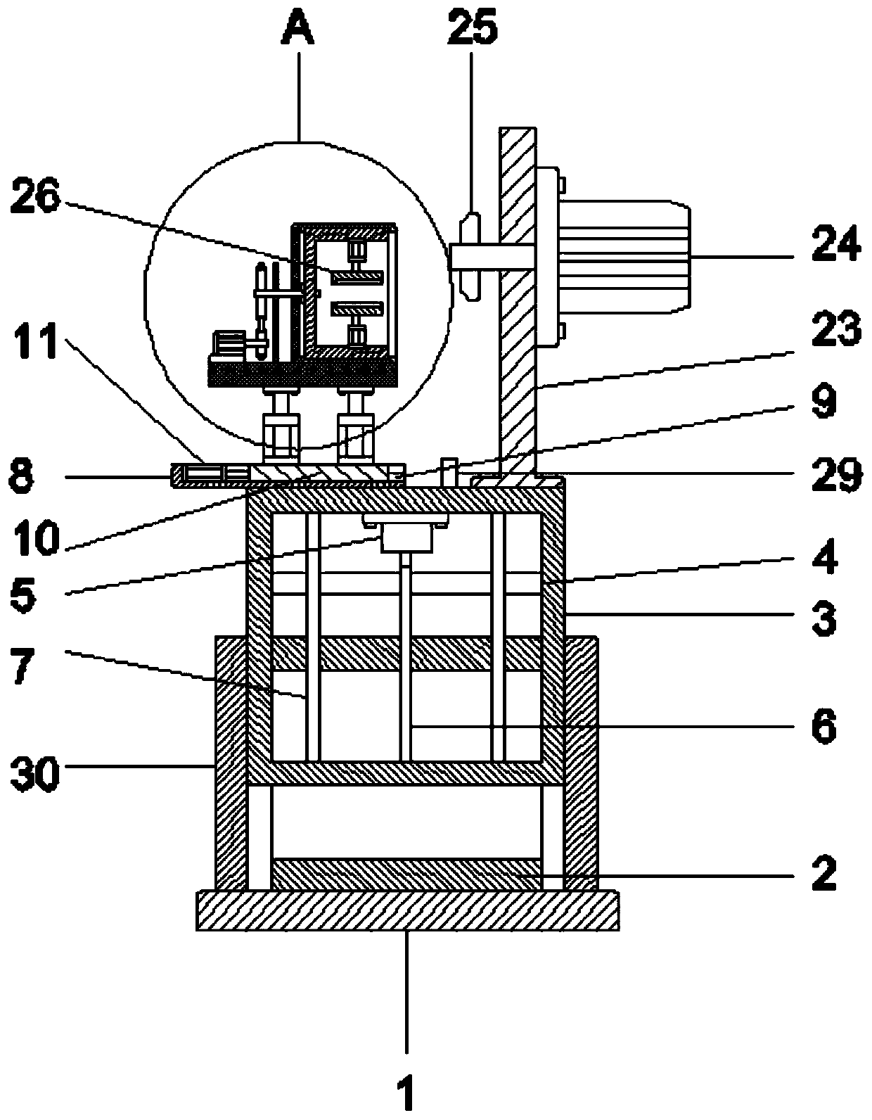
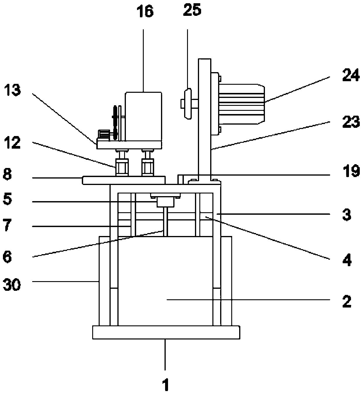
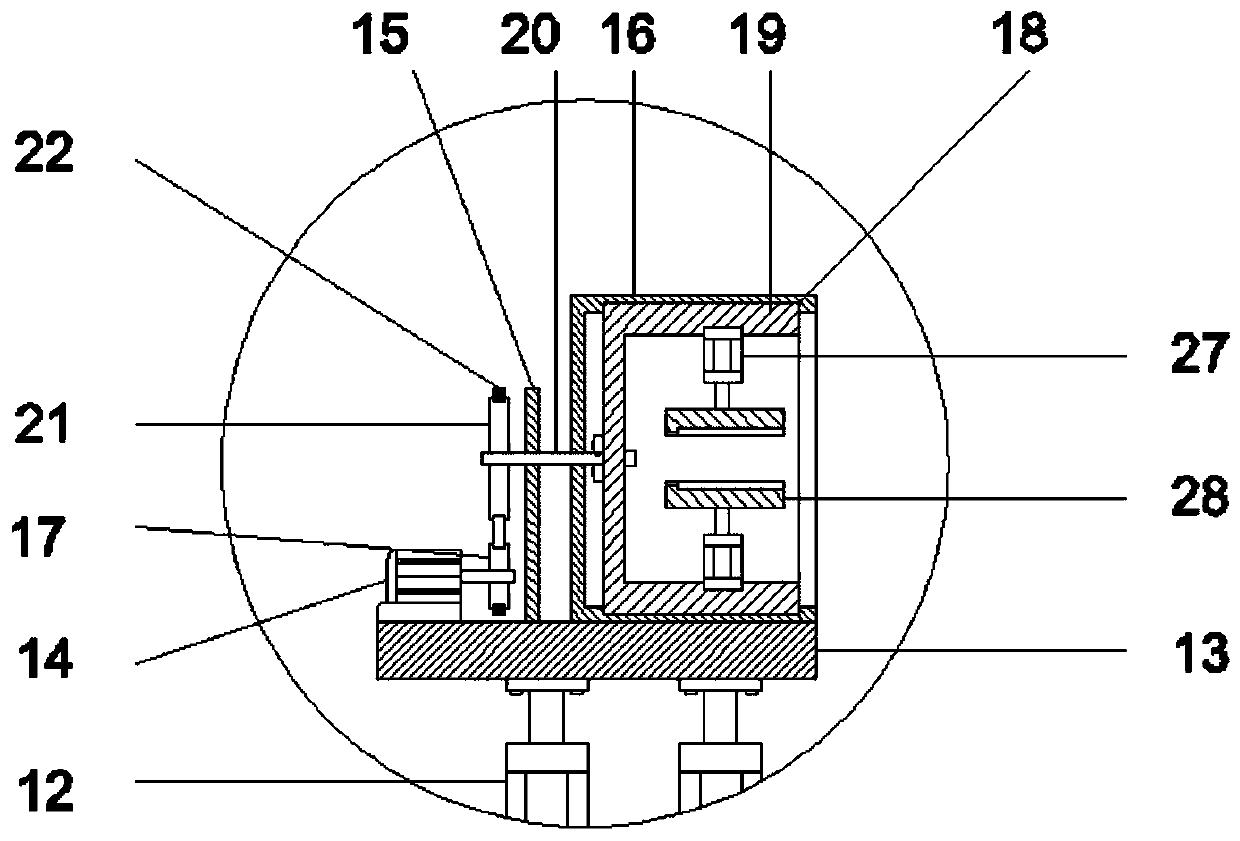
[0021] Such as Figure 1 to Figure 5 As shown, a carbon rod end chamfering device includes a base 1, the base 1 is provided with a lower frame 2, and the lower frame 2 is slidably connected with an upper frame 3, and the inner side of the upper frame 3 is A first motor 5 and a fixed rod 7 are fixed, the output shaft of the first motor 5 is connected with a lead screw 6, the lead screw 6 is rotatably connected to the upper frame body 3, and the fixed rod 7 is slidably connected to the lower frame body 2, the bottom of the lower frame body 2 is provided with threaded holes, the lower frame body 2 is threadedly connected to the lead screw 6 through the threaded holes, the top of the upper frame body 3 is fixed with a first support plate 8, and the first The support plate 8 is provided with a second chute 9, the second chute 9 is slidably connected with a slider 10, the second chute 9 is provided with a cylinder 11, and the telescopic rod of the cylinder 11 and the slider 10 conn...

Embodiment 2

[0024] Such as figure 1 and Figure 5 As shown, a carbon rod end chamfering device includes a base 1, the base 1 is provided with a lower frame 2, and the lower frame 2 is slidably connected with an upper frame 3, and the inner side of the upper frame 3 is A first motor 5 and a fixed rod 7 are fixed, the output shaft of the first motor 5 is connected with a lead screw 6, the lead screw 6 is rotatably connected to the upper frame body 3, and the fixed rod 7 is slidably connected to the lower frame body 2, the bottom of the lower frame body 2 is provided with threaded holes, the lower frame body 2 is threadedly connected to the lead screw 6 through the threaded holes, the top of the upper frame body 3 is fixed with a first support plate 8, and the first The support plate 8 is provided with a second chute 9, the second chute 9 is slidably connected with a slider 10, the second chute 9 is provided with a cylinder 11, and the telescopic rod of the cylinder 11 and the slider 10 co...


PUM


Abstract

The invention discloses a carbon rod end part chamfering device, and relates to the technical field of graphite carbon rod machining equipment. The carbon rod end part chamfering device comprises a base, the base is provided with a lower frame body, the lower frame body is slidably connected with an upper frame body, and a first motor, fixing rods and a lead screw are fixed to the inner side of the upper frame body; a first supporting plate is fixed to the top of the upper frame body, the first supporting plate is provided with a cylinder and a sliding block, and a first hydraulic cylinder isfixed to the top of the sliding block; a second supporting plate is connected to a telescopic rod of the first hydraulic cylinder, and a second motor, a support plate and a cylinder frame are sequentially arranged on the top of the second supporting plate; and a cylinder is slidably connected in the cylinder frame, a rotating shaft is fixed to the left side of the cylinder, a supporting base is arranged on the right side of the first supporting plate, the supporting base is fixed to the top of the upper frame body, a sand mill is installed on the supporting base, and clamping devices are symmetrically arranged on the inner side of the cylinder along the axis. The carbon rod end part chamfering device has a high carbon rod chamfering precision and is suitable for chamfering of carbon rods with different specifications.

Description

technical field [0001] The invention relates to the technical field of graphite carbon rod processing equipment, in particular to a carbon rod end chamfering device. Background technique [0002] Carbon rod is a non-metallic product. As a necessary cutting consumable before welding in the carbon arc gouging cutting process, it is made of carbon, graphite and an appropriate adhesive. It is formed by extrusion and baked at 2200 ° C. It is made of a layer of copper plated after the section, high temperature resistance, good electrical conductivity, not easy to break, suitable for cutting metal into required shapes, generally speaking, for carbon rods used in medical and other fields, one end of the carbon rod needs to be adjusted For chamfering, the chamfering is usually done manually on a grinder, but the carbon rods produced in this way require a large amount of work, and the chamfering size is not uniform. [0003] Chinese patent application CN201420313964.7 discloses a car...

Claims


Application Information

Patent Timeline
Patent Type & Authority Patents(China)
IPC IPC(8): B24B9/06B24B41/06B24B47/12B24B47/20
CPCB24B9/06B24B41/06B24B47/12B24B47/20
Inventor 侯大伟
Owner 亳州市亚珠新材料有限公司
Why Eureka
Try Eureka