

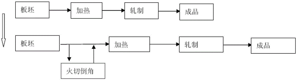
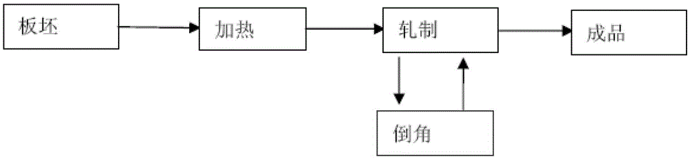
A method of chamfering slabs during rolling by a rolling mill
A slab and chamfering technology, which is applied to the production field of fire-cut chamfering of thick slab slabs, can solve the problems of long time consumption, long chamfering time and increased cost, and achieve the effect of eliminating high cost.
- Summary
- Abstract
- Description
- Claims
- Application Information
AI Technical Summary
Problems solved by technology
Method used
Image

Examples
Embodiment 1
[0109] Slab size: thickness 290mm, width 2300mm, length 2700mm.
[0110] Target size of rolled steel plate: thickness 20.15mm, width 3800mm, length 11740mm.
[0111] The widening pass is calculated as 5 passes, and the first two passes meet the chamfering conditions;
[0112] The thickness of the slab before widening is 265mm; the rolling length is 3800mm of slab width.
[0113] Setting for the first pass of widening:
[0114] The reduction amount is 30mm, the thickness after reduction is 235mm, the length after rolling is Len=4285mm, the calculated temperature is 1121℃,
[0115] Length of head and tail segment Lp=40mm,
[0116] L1=L19=30mm;
[0117] L2=L3=……L18=(4285-2*40) / 17=247mm.
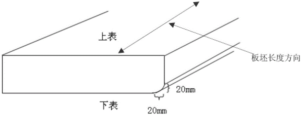
[0118] The chamfer depth is set to h=20mm,
[0119] Roll gap value So=236mm before processing,
[0120] S1p=S20p=So-h=216mm,
[0121] S2=S3=……=S19=236mm.
[0122] Setting for the second pass of broadening:
[0123] The reduction amount is 30mm, the thickness after reduction is 205mm, and the length after rolling i...
PUM
 Abstract
Description
Claims
Application Information